Lesson 50

Lesson Objective: In this lesson, we will learn about the 2D Drafting capabilities and how to create a symbol from scratch.
2D DRAFTING
There are times in drawing mode where you may need to sketch entities. Creating symbols and formats is the most common usage for the 2D drafting tools in drawing mode, but often, we create geometry on the drawing (such as parting lines, arrows, etc.)
The 2D Drafting tools are not the most user-friendly tools in the Pro/ENGINEER drawing arsenal. In fact, compared to the part mode sketcher functionality, the 2D Drafting tools seem very clunky. In a future release of Wildfire, the 2D drafting functionality is going to be replaced by the regular sketcher tools, which will make it much easier to use.
The 2D Drafting tools are located on the feature toolbar in drawing mode, and look like the following:

We will go through these tools in the next section.
2D DRAFTING TOOLS
To demonstrate the different drafting tools, open up the 2D_Draft.drw drawing. It contains three views, as shown in the next figure.

We will work out in the upper right corner for most of these tools, but some of them require actual geometry to work off of, so we will come back to the views in a minute.
Enable Sketching Chain
If you depress this tool, a command remains active until you select a different command. For example, if you start to sketch a line, once you place the endpoint of the first line, it becomes the start point for the next line.
If you don’t have this active, then the line tool is still the active tool, but you have to pick the start of the next line.
We will demonstrate this once we get into the line tool.
Remember Parametric Sketching References
When you sketch draft entities in drawing mode, you can pick on existing draft geometry or view geometry as references (just like we pick references in sketch mode).
If you press this button, and then sketch an entity parametrically related to a view, an update to the model will update the parametric information (collinear constraint, for example). We will see an example of this with the line tool.
Line Tools
The line tool is a fly-out consisting of the following tools.

2 Point Line
The two-point line creates a line by picking on the start point, and then picking on the end point. When you pick on the tool, you will see a red cross-hairs on the mouse cursor as it moves across the drawing, as shown in the next figure.

A window appears for capturing sketching references, as shown in the following figure.

Currently we don’t have any references. We will come back to this in a minute. Out on the drawing, if you hold down the right mouse button, you will see the following options.

The following commands directly relate to the sketch that we are creating. These are:
· Select Reference – Takes us back to the Snapping Reference window that appeared.
· Angle – Specify an angle for the line entity that we are currently sketching or will sketch. To make a horizontal line, enter 0.0 or 180 for the angle. For a vertical line, enter 90 or 270 degrees for the value.
· Relative Coordinates – This is usually used for the end point of the line, giving you exact control of the vector from the start point. For example, a horizontal line exactly 1.5” long going to the right of the start point would result in the following: X = 1.5, Y=0.
· Absolute Coordinates – This can be used for either endpoint. It gives you the ability to sketch using the entire sheet size as a grid, where X=0, Y=0 is in the lower left corner of the sheet. For an “A” size sheet, your maximum X that you would want to go is 11.0”, and your maximum Y that you would want to go is 8.5”.
· Regenerate Draft – Regenerates all of the draft entities. Any parametrically linked entities would update.
· Properties – Select line size, color, style, etc.
We will select Angle, which will give us the following window.

We will keep the default value of 0.0000 to create a horizontal line. Click on <ENTER> on your keyboard, or click on the green check mark to accept this. Click anywhere on the drawing to start the line. As you move your mouse, you will see a magenta preview of the line going to the left or right of your first point (depending on which side you are on when you drag).

We will make this line segment exactly 3.0” in length, therefore, before you select your end point, right click again, and select Relative Coordinates, which brings up the following window.

As indicated in the window above, if we enter 3.0 in the “X” field, we will get a line that is 3 inches long going to the right. If we entered -3.0, it would go 3 inches to the left. Click on the green check mark to accept this, and we get the following line.
In our Snapping References window, we can see the line added to the list of active references.

If we move our mouse back over to one of the end points of the line, we can see that it will snap there for the beginning of our next line.

Go ahead and snap to the right end as shown above, and click to start a new line. As you move your line up, and away from the first line, you will notice that it will snap at perpendicular, as shown in the next figure.

We would use this to make a square or rectangle. Instead, we are going to hold down the right mouse button, select Angle, and enter 135 for the angle. This forces the line to go at 45 degrees with respect to the first line, as shown in the next figure.

Drag the line well over to the right of the middle, and click to create it, as shown in the next figure.

Now, we have two lines in our References window – the first horizontal line and now the new angled line. We will create a third line starting at the left end of the horizontal line, and select Angle and enter a value of 45 to get a line going up towards our last one.
When you get to the first angled line, our new line will snap to it, as shown in the next figure.

Click to accept this snap and finish the line. Click on the middle mouse button to finish out of line mode, and we are left with the following on our drawing.

Trim
We will take a moment to see how to trim a line. From the menu bar, we would select Edit, Trim, which gives you the following options for trimming.

· Divide at Intersection – divides up the entities where they intersect. You can then delete the extra pieces you don’t need.
· Divide by Equal Segments – Breaks up an entity into equal length segments. For example, breaking up a line into 10 pieces of equal length.
· Corner – Trims two intersecting entities at their intersection point. The entities need to either already touch, or project to touch at a corner.
· Bound – Extends an entity up to another one. The entities must project to a corner intersection
· Length – Trims an entity to an exact length by extending or shortening the entity near the endpoint selected.
· Increment – Extends or shortens an entity by a specified amount.
We will choose the Corner option, and then pick on the two angled lines on the portion we want to keep using the Ctrl key, as shown in the next figure.

This will eliminate the small portion that extends out to the upper left, resulting in the following.

Construction Line
The second line tool is the Construction Line. It creates a line just like the two-point line, but it behaves like a sketcher centerline or construction line. It will not print out on a drawing if used.
Select this tool from the line tools fly-out. When the Snapping References window appears, you will notice that there are no references listed. What happened to our three lines that we created? The lines are still there, but their presence in the references window was only while we were still active in the line tool. Once we went back to the select tool, it cleared the references.
Therefore, we will pick on the arrow button in this window to add references, and we will pick on the two angled lines in our triangle. They will show up in the window, as shown in the next figure.

Click on the middle mouse button to finish picking references, and then bring your mouse over to the left of the two angled lines. Around the middle of the line, it should snap to the midpoint, as shown in the next figure.
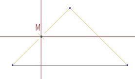
Click here, and then go over to the midpoint on the other line, as shown in the next figure.

When you click on this endpoint, a dashed line appears across the working window. Click on the middle mouse button to complete the creation of construction lines and return to the select tool. We can see a light gray dashed line on our drawing.

Unlike sketcher, where you can convert a line to a construction line, and still have it be within the endpoints selected, this construction line will use the start and end points as vectors to define an infinite line.
Go ahead and use the select tool to drag a box around the triangle to select it, and hit the delete key on your keyboard. Pick on the construction line that we just created and delete it as well.
Crossed Construction Lines
The Crossed Construction Line tool creates two perpendicular construction lines. The first line you draw determines the location of the origin of the lines (where they intersect) by using the start point. The end point determines the horizontal vector. The perpendicular construction line is created automatically.
To demonstrate this, click on this tool from the line tools fly-out icon. Pick out on the drawing, and then move your mouse over and down to create an angled line, as shown in the following figure.

When you click on the end point, the two construction lines appear. The location of the intersection of the two lines is where our start point was before, while the angle of the lines is determined by the end point that we picked, as shown in the next figure.

Go ahead and delete these two lines.
Enable Chain Sketching – Revisited
We will now take a look at this option. If we click this icon, and then go into our line tool, we start to create a line the same way we normally do. This time, however, when you pick on the endpoint for the first line, notice how the next line starts automatically at the endpoint of the first one?

This is similar to the way it works in Sketcher mode with the line tool. To complete your chain of lines, click on the middle mouse button. The line tool will still remain active for you to start a new set of lines. To get back to the select tool, click on the middle mouse button again. Delete any entities that you just sketched. Keep this tool active for our next topic.
Remember Parametric Sketching References – Revisited
Now, we will look at this option again using the line tool. To start, click on the icon to activate this. You must have the icon active before you sketch your geometry. Activating it after will only enable it for newly sketched entities.
Once you have pressed the button, click on the line tool. In the Snapping References window, click on the arrow button, and we will pick the following edge on our RIGHT view.

When we select this edge, its endpoints highlight in a blue dot, as shown in the next figure.

We will see this edge listed in our References window.

Click on the middle mouse button to finish selecting references, and then our line command becomes active. Sketch a perpendicular line starting on the left point of the reference edge (be sure you are snapped to it). Stop the line before you get to an “equal length” condition between the line and the edge. The next line segment should start automatically (because we still have our chain sketching enabled). Sketch a horizontal line over until you get an equal length condition with the edge, then create the last segment down to the right vertex of the edge. The following figure shows this sketch.

To demonstrate the parametric nature of our references, we will change a model dimension to force the top edge of the model to translate down. To do this, we will show some dimensions.
Alternate way to Show Dimensions
Another way to show dimensions on your drawing for a specific feature is to go to the model tree, right click on the feature, and select Show Dimensions, as shown in the next figure.

Unlike the Show/Erase tool, we have no ability to only select certain ones to keep, but that is okay for this instance. On our drawing, we can see the three dimensions that make up our selected feature.

We will select on the 2.000 dimension once to activate it, and the double-click on it to modify the value to 1.5. Regenerate the model, and you will notice that as the top edge of the model translates down, the sketched entities move with it to remain snapped to the edge, as shown in the next figure.

Edit the dimension back to 2.000, regenerate the model, and then delete the three sketched entities that we made.
By contrast, if we try this same thing again without using the Remember Parametric Sketching References activated, the sketched entities will not translate with the top edge, as we can see in the following figure.

Try this out for yourself by repeating this same process, but de-select the tool first. When done, set the dimension back to 2.0, and regenerate the model. Delete the sketched entities. Finally, de-select the Chain Sketching command.
Circle Tools
The circle tools is a fly-out consisting of the following.

Circle Tool
To create a circle, click on the drawing, and then drag out the diameter. Click to complete the circle. If the Chain Sketching is active, a new circle starts again at the same center, allowing you to create concentric circles.
If you click with the right mouse button with the circle tool active, you see the following.

This is very similar to the RMB functionality with the line tool, but instead of an Angle to define, we can specify the Radius. When we select this option, we get the following window.

We will enter a value of 1.0 in this field, and then click on the green check mark, or hit the <ENTER> key on the keyboard. When we do, we see the outline of the circle at the specified dimension.

We then click to place the circle. Remember, this is the RADIUS of the circle that we entered, not the DIAMETER. The following shows the circle after it has been created.

Delete this circle when complete.
Construction Circle
This is done exactly the same as the regular circle. The only difference is that the circle that results is only used to aid in the creation of other entities, and will not print. It is a dashed gray entity, just like the construction line.

Ellipse by Major Axis End Points
The first ellipse tool is created by first selecting the start point and then end point of a line that represents the length of the ellipse. This line can be at any angle you want. The following figure shows the creation of this first line.

Once you pick on the end point, the ellipse will appear, and you can drag out the width, as shown in the next figure.

The following figure shows the created ellipse.

Delete this ellipse.
Ellipse by Center and End of Major Axis
The last ellipse is very similar to the previous one. The biggest difference is that instead of picking the start point of the line that defines the length, we are picking the center of the ellipse. Once we pick on the location, the line grows out on both sides of this point, and rotates about it. Once you pick the second time to finish dragging out the length, you drag out the width of the ellipse just as we did before.
Arc Tools
The Arc Tools is a fly-out icon that contains the following:

3 Point/Tangent-End Arc
Click on the 3 Point/Tangent Arc tool and click out on the drawing. This creates the start point for our arc. Next, drag your mouse over to the location for the end point, as shown in the next figure.

When you click on the end point, you now drag out the radius of the arc, as shown in the next figure.

When you click once more, you finish the first arc. Since the arc tool remains active, we can go straight into demonstrating the tangent-end arc. Therefore, bring your cursor over the end point of the arc that we just created, and you will see it snap to this point. A small “T” appears to indicate that it will be tangent, as shown in the next figure.

Click on this end point to start the arc, and then drag out the end point for the tangent arc, as shown in the next figure.

When you click to place the end point, we can continue to make additional arcs, or click on the middle mouse button to complete the arc tool. The following figure shows the completed set of arcs.

Delete these arcs when done.
Center-Ends Arc
When you click on this tool, the first point you will pick is the center of the arc. Once you pick the center point on your drawing, a circle will appear. Your cursor will ride on the circle to define the start point of the arc, as shown in the next figure.

Once you click to create the start point, you are now dragging out the location on the circle where the end point will be, as shown in the following figure.

The following figure shows the completed arc.

Delete this arc when done.
Fillet Tools
The fillet tools is a fly-out, but there is only one fillet tool in our current fly-out. This is the Round Fillets Tangent To 2 Edges command.
To demonstrate this, first create two lines that connect to each other, as shown in the next figure.

Now, click on the fillet tool, and you will be asked to select one entity. We will pick on the first line as shown below.

Next, we will pick on the second line. Once we pick on the second line, a prompt appears in the message bar, as shown in the next figure.
![]()
We will enter 0.75, as shown in the figure above. When we do this, an arc appears on the sketch, as shown in the next figure.

Click on the middle mouse button to complete the arc tool, and you will see the following on your drawing.

Delete these entities when done.
Spline Tool
To create a spline, start by selecting on this tool to activate it. Next, pick on the first endpoint of the spline, and then continue to pick intermediate points. When you have picked your last point, click on the middle mouse button to complete it. The following figure shows a spline as it is being defined.

Once you click on the middle mouse button (after picking the end point), you will see the end points highlighted in blue, while the intermediate points are in the curve color, as shown in the next figure.

Click on the middle mouse button again to exit out of the spline tool. The following figure shows the completed spline.

Delete this spline when done.
Point Tool
The Point tool creates a single point on the drawing. The following figure shows some completed points.

NOTE: The shape and size of the point can be controlled by the drawing setup file. There are two options:
· Datum_point_shape – Controls the shape of the point. The values available are:

· Datum_point_size – Controls the height of the symbol used for the point.
Delete these points when you are done.
Chamfer Tool
The chamfer tool adds an angled line at the intersection of two entities. To demonstrate this tool, first start by creating two connecting lines, as shown in then next figure.

Now, click on the chamfer tool. This brings up the following menu.

From here on out, we will assume that when prompted to select the entities, that we will pick the following lines in the order shown in the next figure.

When you click on one of the schemes, you are then prompted to pick the entities. Once we pick the entities in the order shown above (using the Ctrl key), a blue circle appears at the intersection, and the message bar prompts us for the necessary chamfer values.
45 x d
You are prompted to pick the value for d. We will enter 0.5. It automatically measures the 45 degree angle from the first line picked. The chamfer is added. The following figure shows the resulting scheme for this chamfer.

The value for d is measured along the first line selected. To get back to the line before we added the chamfer, click on the Undo button, or delete the chamfered edge, and then use Edit, Trim, Corner and select the two lines again using the Ctrl key.
d x d
You are prompted to pick the value for d. We will enter 0.5. The chamfer is added equally to both lines, as shown in the next figure.

Undo this chamfer or trim to get back to the starting two lines.
d1 x d2
You are prompted to enter the value for d1. Whatever line you pick first will have d1 measured along it. We will enter 0.5. We are then prompted for d2, and we will enter 0.625. The chamfer is created as shown in the following figure.

Undo this chamfer or trim to get back to the starting two lines.
Ang x d
When you click on this option, you are asked to pick the reference line. This will be the line that the distance and angle are measured from. We will still pick the first line as indicated in an earlier figure. We then pick the second line.
We are prompted to enter a value for d. We will enter 0.5. For the angle (measured from the first line), we will enter 20.0. This creates the chamfer with the following scheme.

Delete these lines when done.
Edge Tools
The Edge Tools icon is a fly-out that contains the following:

This tool allows you to create draft entities right on, or offset model edges or datum curves on the drawing. You might want to use this tool to show parting lines in a different line style than the existing drawing entities, or for identifying a surface boundary for a special finish, etc.
Use Edge
To demonstrate this, go to the FRONT view, which currently looks like the following.

We want to indicate a parting line for this view. Therefore, we will click on the Use Edge tool, and select (using the Ctrl key) the following entities on this view.

Once you have all the entities selected, click on the middle mouse button to accept this selection. In the message bar, you will get the following prompt.
![]()
In this particular case, we do want to erase the edges, because our copied draft entities will be right on top of the existing lines, and if we change the line style, we don’t want the model edges to interfere with the visibility of the lines. Therefore, click on Yes. You are then told that you will need to refresh the drawing views.
To do this, click on the following icon in your drawing toolbar.
![]()
Now, select each of the entities that we just created, and right click on them and select Line Style, as shown in the next figure.

This will bring up the following window.

To get a nice dashed line, we will pick on the CTRLFONT_S_L option, as shown in the next figure.

Click on Apply, followed by Close to see the new style on the view.

Now, we can use Edit, Trim, Increment and extend each end 0.5 inches, to get the following.
The nice thing is that the Use Edge command keeps the entities tied to that view, so if we move the view around, the entities move with it.
Offset Edge
To demonstrate the offset edge tool, we will look at the TOP view in our drawing. Click on this tool, and you will get the following menu.

The default option is Single Ent, which stands for “single entity”. If you use this option, then you can only pick one edge at a time and enter the offset right after picking it. If you want to offset more than one edge that forms a chain, use the Ent Chain option. We will use the Ent Chain option for our selection.
Next, using the Ctrl key, select the following edges to offset.

Once all edges are selected, click on the middle mouse button. An arrow will show up on one of the selected entities, as shown in the next figure.

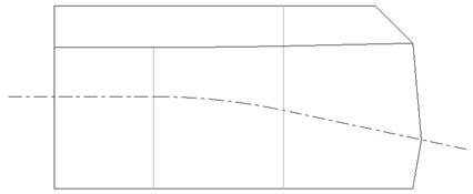
Enter the offset distance where positive is going in the direction of the arrow. For our example, we will enter -0.05 (negative). This will add the following entities to our view.

We will change the line style for these entities to the CTRLFONT_S_L style that we used before, and we get the following.

We will repeat this same process to offset the circle in this view as well. Once we have both sets of offset edges created and set to the CTRLFONT_S_L line style, we will select all of them by dragging a box around the view.
Next, go to Edit, Fill, Hatched and down in the message bar, you are asked to enter a name for the hatched surface. Give it any name you want. I will use SURF_A. When you accept the name, hatch marks appear on the view, as shown in the next figure.

The following menu also appears.

We will click on Spacing, followed by Half (four times) to get the following.

Doing this can make it clear to a manufacturer any comments you might have that require the application to the entire surface, such as a finish note, etc.
On the Fill menu, there is also a Solid option, which will create a shaded surface in this region. You can then go to the properties of the filled area and change the color for more emphasis in electronic mode, as shown in the next figure.

These are just some examples where the edge tools can be used. Save the drawing.
Mirror Tool
The mirror tool is the last toolbar icon. It is used to mirror draft entities about a draft line. Therefore, we will start by creating a series of lines on our drawing as shown in the next figure (NOTE: do not worry about the exact shape and size, just get it close).

Now, sketch a single line at an angle to the right of this shape, as shown in the next figure.

To mirror the sketch, start by clicking on the mirror tool. Drag a box around the closed sketch (don’t include the angled line). These entities highlight in red. Click on the middle mouse button to finish selecting the objects to mirror.
Down in the message bar, it prompts you to pick on a draft line to mirror about. We will pick on the angled line that we sketched. When we do this, we can see the new mirrored entities, as shown in the following figure.

Delete these entities when done.
SKETCH MENU & OTHER DRAFT TOOLS
Up to now, we have focused primarily on the 2D Drafting toolbar. We will now take a look at other, related drafting tools in drawing mode.
Sketch Menu
In the menu bar, there is a sketch menu. If we click on it, we get the following.

For the most part, this menu contains all of the commands that are covered in the icons that we have gone over. We will look at one in particular, called Sketcher Preferences.
When we click on this, it brings up the following window.

This menu controls the automatic snapping constraints that can be applied while sketching. For example, if you recall when sketching in previous sections, we saw that the entities snapped to each other and their vertices. These are on by default in this sketcher preferences window.
We can see that we can enable Horizontal and Vertical snapping, which would be very useful to save us some time in specifying right mouse button commands.
We will enable this, and the Angle snapping (leave at 45 degrees). Now, try sketching lines on your drawing. You can see that the objects will snap at 45 degrees, as well as horizontal and vertical orientations.
Transform
In the Edit menu, there is a command called Transform, which gives you the following options.

This set of commands will let you move, move and copy, rotate, scale, mirror and stretch your draft entities.
Translate / Translate and Copy
To demonstrate the translate functionality, go ahead and sketch a circle with a radius of .25 located at absolute coordinates of X=6.0 and Y=6.0. This will create the circle as shown in the next figure.

Now, we will go to Edit, Translate. We are asked to pick on the entities to translate. We will pick on the circle, and then click on the middle mouse button to finish selecting objects. This will bring up the following menu.

The options at the top are:
· Horiz – Enter a distance in the X-direction.
· Vert – Enter a distance in the Y-direction.
· Ang/Length – Enter a distance in polar coordinates
· From-To – Enter a distance by taking a vector using one of the methods in the second section.
The second section gives the following options:
· Pick Pnt – Pick a point on the screen for the start/end of the vector.
· Vertex – Select a vertex for the start/end of the vector.
· On Entity – Pick a point on a draft entity for the start/end of the vector.
· Rel Coords – Pick a point a certain x and y distance from the current circle center for the start/end of the vector.
· Abs Coords – Pick an exact x and y location for the start/end of the vector.
NOTE: You can use one option for the start, and a different option for the end of the vector. For example, you could pick Vertex for the start of the translation vector, and then use Rel Coords to locate the end of the vector.
We will use Horiz in the top menu, and enter a value of 1.0. The circle will move 1 inch in the X direction.
Now, we will click on Edit, Transform, Translate and Copy, and pick on the circle again. After using the middle mouse button to accept the selection, pick on Horiz again, and enter 1.0 for the incremental distance between copies. Once you enter this number, you are prompted for the number of copies. The number that you enter does not include the first circle, so if you want a total of 10, you need to enter 9. We will enter 3, and then hit the <ENTER> key. we should see three additional circles created, each spaced 1.0 inch from each other, as shown in the next figure.

Delete all four circles.
Rotate / Rotate and Copy
These commands are similar to the Translate and Translate and Copy commands. We will first start by sketching the following shape on our drawing.

We are going to rotate the triangular object about the center of the circle. Therefore, go to Edit, Transform, Rotate, and then drag a box around the two lines and the arc that make up the piece to rotate (don’t include the circle in the box).
Once all three objects are selected, click on the middle mouse button. We will get the following menu.

We will use the Vertex option to be able to select the center of the circle/arc. Once you pick this option, move your mouse over to the center of the circle. You should see a light blue circle appear at the center. Click on this vertex, and then you will get the following prompt in the message bar:
![]()
We will enter 90 as shown above, and then click on the <ENTER> key on our keyboard. The draft entities will rotate to the bottom of the circle, as shown in the next figure.

Now, we will try out the Rotate and Copy command to make five of these wedges equally spaced about the circle. Therefore, click on Edit, Transform, Rotate and Copy. Drag a box around the entities again, and then click on the middle mouse button.
Select Vertex once more from the menu, and pick on the center of the arc/circle. When prompted for the angle of rotation, we will type in 360/5 (you can enter equations in dimension fields).
For the number of entities to create, we will enter 4 to create a total of five of these wedges. The result will be the following.

Keep these entities on the drawing for the next topic.
Rescale
We are now going to see how to scale the object. Currently, the scale is at 1.0. To make this half as big, we would enter a scale of 0.5. Once the object is scaled, it is reset at 1.0 again, so to make it half as big again, we would still use 0.5 (not 0.25 from the original starting size).
Therefore, click on Edit, Transform, Rescale. Drag a box around all of these objects to select them, and then click on the middle mouse button. We will get the following menu.

We are asked to select the point/vertex about which to scale. The point that we pick will remain where it is, and the rest of the entities will scale about that point, potentially causing some translation if you pick an extremity as the scaling point (such as one of the tips of the wedges).
We will click on Vertex, and select the center of the circle to scale about. When we do this, we are asked to enter the scale in the message bar. Enter 0.5, and then hit the <ENTER> key on your keyboard.
The entities scale down to half of the original size, as shown in the next figure.

We will use these entities once more for the next topic.
Stretch
We are going to skip over Mirror, because we already covered this as a tool on the 2D Drafting toolbar.
The Stretch tool is used to elongate or shrink the draft entities, but not proportionally (like a scale command). Therefore, we will go to Edit, Transform, Stretch. You are asked to draw a box about the entities to stretch. NOTE: Unlike the previous commands where you had to get the box around the entire entity to select it, this time the box only has to touch the entities to select them.
We only want to stretch out the bottom wedge, so we will draw a box that only touches the two angled lines on the bottom wedge. Do not touch the arc at the top of the wedge, or any other entities on this drawing.
Once both lines are selected, click on the middle mouse button. We get the following menu.

The stretch command uses the translate option to define a vector for the length and direction of stretch. We will start by selecting Vertex, and then picking on the following vertex to act as the starting point of our vector.

Once you pick this vertex, you are prompted to define the end point. We will use Rel Coords to enter an X and Y translation from the selected vertex. When prompted, enter X=0 and Y=-0.5. This will result in the following.

Group
Create
We will now talk about grouping objects. If you were to select just one of the entities in this current set of draft objects, you could then drag it and it would separate from the rest of the entities.
Even though we snapped to end points when defining the sketch, the entities are not completely connected. Therefore, we will want to group these entities together to be able to manipulate them as a single entity.
Therefore, go to Edit, Group, Draft Group from the menu bar. This brings up the following menu.
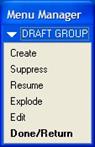
We have the ability to create groups, suppress them, resume any suppressed groups, ungroup (explode) and edit groups within this menu. We will click on Create, and then drag a box around all of the draft entities. Click on the middle mouse button to finish selecting objects, and then in the message bar we will be prompted to enter a group name. Type in STAR, and then hit the <ENTER> key.
The group is created, and now we can select additional entities to group. Click on the middle mouse button to finish creating draft groups.
Now, if you try dragging just one entity, the entire group moves.
Edit
To edit a group, click on Edit, Group, Draft Group, and then select Edit from the menu. This brings up a sub-menu, as follows:

You can either select the group from the drawing (which is the default), or you can pick from a list of created group names. We will click on By Name, which brings up the following.

We can see the current group that we created, called STAR. Pick on this name, and you will get the following options.

We can add additional entities to our group, or remove current entities from the group. To cancel out of this, click on the middle mouse button.
Additional Comments
The thing that makes 2D drafting less user friendly than regular sketch mode (intent manager), is the fact that you should be more exact in your sketching, because making changes to your sketch is more difficult.
Dimensions can not be modified to shorten, lengthen, or move draft objects. Therefore, if you sketch a rectangle using four lines, you can add dimensions. To get the exact length and width of the rectangle, you would need to either do this up front, or trim to length the entities after the fact. Once you trim to the length, the entities become disjointed, and you will need to translate other entities to get it back.
Therefore, I highly recommend being precise up front.
SYMBOL CREATION
Creating a symbol is an extension of 2D Drafting – since most of what you do involves sketching the shape of the symbol.
The advantage of creating symbols is to create a library of commonly used shapes that appear in the drawing. You can also scale symbols upon retrieval, so changing the size is easier.
To demonstrate this, we will continue to work in the same drawing, but delete any draft entities in the drawing already.
Starting a New Symbol
To start a new symbol, you go to Format, Symbol Gallery from the menu bar. This will bring up the following menu.

The options in this menu do the following:
· Define – Create a new symbol
· Redefine – Change an existing symbol
· Delete – Delete a symbol from the library
· Write – Save the symbol to the library
· Symbol Dir – Define the directory where you will save symbols for this session.
· Show Name – Pick on a symbol in your drawing to identify the symbol name in the library that represents the symbol.
Symbol Dir
Normally, our symbol library is governed by our Config.pro file, as we saw in Lesson 49 – GTOLS and Symbols. For the purpose of this training guide, we do not want to write our temporary symbols to this location.
Therefore, we will need to use Symbol Dir to select our current training directory as the location to save any symbols we create. Click on Symbol Dir, and you will get the following.

We can see that the current directory is our Symbols system folder. Therefore, click on the Working Directory icon (the one with the little blue diamond in the upper right corner), followed by Open.
Down in the message bar, we see the confirmation that our working directory is now the active symbol library directory, as shown in the following figure.
![]()
Define
We will now define a new symbol. Therefore, click on Define in the menu manager. Down in the message bar, we are prompted to enter a symbol name. We will enter MY_SYMBOL for the name, and then hit the <ENTER> key on the keyboard.
The following menu manager appears:

On our working window, it looks as if all the drawing entities and views have disappeared. In reality, a new window has opened with a blank drawing sheet. In the title bar at the upper left corner of the Pro/ENGINEER interface, we can see that our symbol is currently active, as shown in the following figure.
![]()
We can start to define our symbol in this blank drawing. The location of the symbol on the drawing is not important, but the shape and size of the symbol is important. We want to create a series of entities that will ultimately allow us to pick the shape of the symbol when we use it.
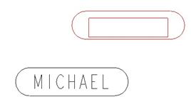
We are going to create three possible shapes for this symbol: Rectangle, Oblong and Oval, as shown in the next figure.
![]()
For each of these symbols, we want the ability to show text in the center (as shown above), or not have text. This text has to be different every time it is used, so it must be variable. In addition, we want the ability to place these symbols on the drawing without leaders, or with a leader on the left or right side of the symbol.
Sketching The Rectangle
The first thing we are going to do is sketch our rectangle. From a size standpoint, we should consider what is more critical, the length or the height. We also want to understand what the relationship is between the two.
Why do we care? When we bring in a symbol instance, we have the ability to scale it. Therefore, it makes the most sense to pick whether the length or the height is going to be the driving force behind the scale. For example, if we needed to have a 1” long rectangle one time, and a 2.5” rectangle the next, then we should make the length the driving force behind the size of the rectangle.
If we make the length 1” in our symbol definition, then we can directly scale it to the size we want. If we sketch the rectangle at 2” in the symbol, we would have to scale it to 0.5 to get a 1” rectangle, for example.
Therefore, we will assume that our rectangle is going to be 4 times longer than it is high. So we want to sketch a 1.0 x 0.25 rectangle on our drawing. Use the tools that we have learned in this lesson to create it, as shown in the next figure.

Now, before we go any further, we might want to turn on grid lines, and snap to grid. To turn on the grid lines, you will select View, Draft Grid from the menu bar. This brings up the following menu.

We will click on Show Grid to see the grid lines on the drawing. Currently we see the following.

We can see that the grid is too large to be useful, and the lines don’t sit squarely on the rectangle that we have sketched. Therefore, we will start by re-sizing the grid. Click on Grid Params, which brings up the following:

We can control the X and Y spacing equally (X&Y Spacing), or set them independently (X Spacing and Y Spacing). We can also change the Angle of the grid. We will pick on X&Y Spacing, and then enter 0.0625 in the message bar.
The grid changes to the following.

Clearly, this grid size is better, but the location is not. Therefore, click on Done/Return to get back to the previous menu. On this menu, click on Origin, and select Vertex as the method to select the origin. Pick on the lower left corner of the rectangle, and you will see the grid shift. A coordinate system appears at the origin, as shown in the next figure.

To snap to the gridlines for additional sketching, we will need to go to Sketch, Sketch Preferences, and then click on the Grid Intersection option to activate it. Click on Close, and now we can start to sketch again.
Variable Text
We are now going to add the text inside the rectangle that will become the variable text in the symbol. If you remember from Lesson 49, variable text is a text note that has backwards slashes around it. Therefore, we will go to Insert, Note from the menu bar, which brings up the following menu.

Many of the options are grayed out while in symbol definition mode. We will leave most of the defaults, but we will change the justification of the text to Center, and then click on Make Note.
For the location of the note, click on the grid intersection at the center of our rectangle. Down in the message bar, we will enter \TEXT\ for the note. Be sure to use the back slash before and after the word. Click on <ENTER> twice to finish the note. Our rectangle now looks like the following.

We will want to adjust the text height to make sure it is the correct size for our symbol. We want the text height to be fixed at 0.125 inches. Therefore, click once on the note to select it, and then right mouse click and select Text Style. This brings up the following window.

Currently, the text height is being driven by the drawing setup file at 0.12 inches. We will uncheck the Default box for the height field, and then enter 0.125, as shown in the next figure.

Click on OK, and you will see the text change slightly. We are now ready to create our first grouping of entities.
Group 1 – Rectangle
The grouping functionality for symbol definition is slightly different from what we saw in the 2D Draft Group section earlier in this lesson. We will pick on Groups in the menu manager. It brings up the following menu.

Click on Create. In the message bar, you are prompted to enter a name for the group. Enter RECTANGLE and then click on the <ENTER> key. You are now asked to pick the entities to include in this group. Using the Ctrl key, pick the four sides of the rectangle, and also the text note. Click on the middle mouse button once all of these five entities have been selected. You will get a confirmation that the group has been created.
Group Attributes
Currently, we are defining groups for the top level. We will define the attributes for this level of groups by going to Group Attr, which brings up the following menu.

We want to specify whether the groups at this level are exclusive or independent. Exclusive means that only one option can be selected at any time. If you remember back to when we added a weld symbol, there was a top level that had two or three choices. Only one choice could be selected from this level. This is an example of Exclusive.
Independent means that we can include more than one option from the list in the symbol instance. In the weld symbol that we worked with earlier, you remember how we added two different text notes to the same symbol. These were independent group options at a sub-level.
We will click on Exclusive to ensure that we can only show one of the shapes at any given usage of the symbol. Click on Done/Return to get back to our original symbol menu.
We will now sketch our oblong shape.
Sketching the Oblong
We can sketch our oblong shape directly on top of the rectangle, but that might get a little confusing. Therefore, we will sketch the following shape above the rectangle:

Then, we can translate this down to its correct position, as shown in the next figure.

Now, we can click on Groups, Create and enter OBLONG for the group name. When selecting the entities, be sure you are getting the shorter line on the top and bottom, as well as the two arcs and the text note (we need this text note in all of our groups).
Sketching the Oval (Ellipse)
Now, we will repeat this same process to create the oval shape. The final sketch should look like the following.

Create another group called OVAL, and include the ellipse and the text note for this group. Click on Done/Return from the groups menu when done.
Symbol Attributes
Now that we have finished defining the entities and groups that make up our symbol, we are ready to define the symbol attributes. Therefore, at the SYMBOL EDIT menu, click on Attributes. This brings up the following window.

This window contains two tabs at the top. The General tab is used to define most of the attributes for the symbol, while the Var Text tab is used to define the variable text in the symbol.
Allowed Placement Types
On the General tab, the first section is used to define how the symbol will be placed on the drawing. The choices are:
· Free – The symbol can be placed anywhere on the drawing with no leaders.
· On Entity – The symbol is tied to a geometric entity, such as an edge or vertex on the drawing view.
· Normal to Entity – The symbol will have a leader normal to the entity selected.
· Left Leader – A leader will be on the left side of the symbol.
· Right Leader – A leader will be on the right side of the symbol.
· Radial Leader – A leader will be attached to a circle, and free to travel around the circumference. Since we don’t have any complete circles in our symbol definition, this option is currently grayed out.
You can select more than one type of placement for a single symbol instance. If you recall, we want to be able to bring the symbol in with or without a leader, and the leaders should either be on the left or right side of the symbol. Therefore, we want to pick Free, Left Leader and Right Leader.
For each of these, you will need to pick the location on the symbol where the leader line goes to. The following figure shows where we would pick for each of these options.

Symbol Instance Height
The next section is used to define the height of the symbol. The choices are:
· Fixed – The symbol height is driven from the original definition, and can not change. I do not recommend this, because you won’t be able to scale it or change the size later.
· Variable - Drawing Units – The height is driven by the units on the drawing. For example, if the drawing is in inches, then the height is governed by inch values, even if the model is metric.
· Variable – Model Units – The height is driven by the units of the model. For example, if the model is metric, and the drawing is in inches, then you will be governing the height in mm.
· Variable – Text Related – You will pick on a text note in the symbol to drive the height. If you later modify the height of the text, the symbol will grow/shrink accordingly. The unit of height for the text is governed by the drawing units.
We will pick on Variable – Text Related, and then pick on the “\TEXT\” note in our symbol as the driving text for the height of the symbol.
Attributes
The last section on this tab defines how the leaders and text behave. The options are:
· Fixed Text Angle – The text can not be rotated in the event the symbol is rotated.
· Allow Elbow – Allows jogs in the leaders if defined.
· Allow Geometry to Mirror – Allows you to mirror the symbol geometry
· Allow Text to Mirror – Allows text in the symbol to mirror when the symbol geometry is mirrored.
· Allow Text to Flip – Allows the text in the symbol to be flipped and rotated to maintain its original orientation as the symbol is rotated through 90 degree increments.
We will keep the default settings for this section.
Variable Text
Now, we will click on the Var Text tab at the top of the attributes window, and we will see the following.
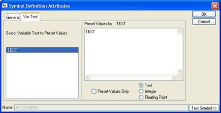
The left side of this window lists all text notes that it finds that have back slashes around them. In this case, we only defined one text note.
The other large field is used to pre-define values that are available for the symbol. By default, it put the current text in the field. Just to see what this does, add the following words to your list of preset values:

Down at the bottom of the window, we can see some check boxes. The first (Preset Values Only) is used to force people from only choosing from the list of preset values (like the ones that we just entered). If you leave it unchecked, you can type in whatever you want for the value or pick from a list. We will leave it unchecked.
The other three boxes are used to define the type for the variable text. Currently, any value we put in (regardless of numeric or alphabetic characters), will be treated as a text string. If we only wanted to use numbers in this field, we could pick on Integer or Floating Point.
We will leave it alone at Text. The last thing we can do is add any symbols to our list of preset values by clicking on the Text Symbol button in the lower right corner. This is the same symbol tool we saw when creating notes or changing the properties of dimensions.
Click on OK once you have completed all of these attribute settings. Click on Done to complete the definition of this symbol.
Write
Now, we will click on Write to save our symbol to our working directory. If we fail to do this, the symbol will remain available in this session, but as soon as we exit out of Pro/E it no longer exists.
When you click on Write, you get the following.
![]()
This gives you a chance to enter a new directory path to store your symbol, but we will just click on <ENTER> to accept the current location (which is the one we set earlier). You will get the following confirmation: “Symbol [C:\Data\Proetrain\Drawing\my_symbol.sym.1] has been stored.”
Here, we can see the full path to the location of the symbol, and the name of the symbol is my_symbol.sym.1.
Using the New Symbol in Our Drawing
Now, we will test out this new symbol that we created by using it in our current drawing (which should now be back up on the screen). Therefore, go to Insert, Drawing Symbol, Custom. The symbol instance window should appear with the symbol that we just created. If not, click on your Working Directory icon from the Open window that appears, and then open the symbol that we just created.
It should look like the following:

We can see that the rectangle version of this symbol is currently active. It is also a good time to point out something critical. If you remember, we used a 1.0” dimension to define the length of our rectangle. Unfortunately, the height of the symbol is being driven from the text height (which by default is 0.12 as defined in the drawing setup file). If you recall, we made the symbol dependent on the text note.
Not a big deal, we can live with this, but you will want to make a mental note that 1) height is the most important dimension when text is not being used to drive it, and 2) the text height drives it when you do specify this attribute.
We will enter 0.25 for the height of the symbol. For now, we will also leave the placement type as Free.
Click on the Grouping tab, and you will see the following.

You can see the three groups that we created in the symbol. Try picking on each of them to see the shape update in the right side of this window. You will also notice that we can only select one of these options at a time (based on the Exclusive group attribute that we defined).
We will select OBLONG for our first symbol instance, and then click on the Variable Text tab, which looks like the following.

We can see our text note is listed as variable text, and we can also see if we use the pull-down field, that our preset values are there, as shown in the next figure.

NOTE: The order in which you entered these preset values is the order that shows up here. It does not automatically sort the words/numbers, so keep that in mind if you want to make a large list of possible values for your symbol.
We will enter our own names in the field instead of picking from the list, and then click anywhere on the drawing to place the first symbol. Our first symbol instance is created, and an outline appears immediately for any additional symbols we want to create, as shown in the next figure.
Go back to the General tab. This time, we will change the placement type from Free to With Leaders. When we do this, we see the menu for placing the leader. We will use the On Entity and Arrow Head options (that are there by default), and select on the following edge on the TOP view.

When we do this, we can see a preview of the symbol appear on the drawing.

Click on the middle mouse button to finish the placement for this symbol instance, and you will see it as shown in the next figure.

Click on OK to complete the definition for these two symbols. Try moving around the symbol with the leader, you will notice that you can move the symbol to the other side of the leader line, and an elbow appears automatically. You will also notice that the leader which was on the left, automatically jumps to the right side if the symbol is moved to the left. The following figure shows this.

Save and close this drawing.
LESSON SUMMARY
2D Drafting in drawing mode is somewhat clunky compared to the robust sketcher used in part mode. This will change in a new release. For now, this lesson teaches you how to use the 2D Drafting tools, and some best practices for using them.
Symbols are used to reproduce common draft sketches. You can create simple symbols, or even multi-level symbols with groups and variable text.
EXERCISES
None