Lesson 49

Lesson Objective: In this lesson, we will learn how to create Geometric Tolerances (GTOLS) and how to access symbol libraries.
DEFINITIONS
Before we jump into Geometric Tolerances, we will take a moment to look at some definitions that pertain to concepts behind GTOLS. These definitions come from the ASME Y14.5 standard.
Datum
A Datum is a theoretically exact point, axis or plane. It is the origin from which the location of geometric characteristics of features of a part is established. For example, if we specify the bottom, planar surface of a model as a datum, then defining a “parallel” tolerance to that surface assumes that the datum surface is (for all intents and purposes) perfectly flat. We already learned how to define a datum (planar and axial) in Lesson 46.
Feature of Size
One cylindrical or spherical surface, or a set of two opposed parallel surfaces associated with a size dimension.
Least Material Condition (LMC)
The condition in which a feature of size contains the least amount of material within the stated limits of size. For example, the maximum hole diameter and minimum shaft diameter.
Maximum Material Condition (MMC)
The condition in which a feature of size contains the maximum amount of material within the stated limits of size. For example, the minimum hole diameter and maximum shaft diameter.
Regardless of Feature Size (RFS)
This term is used to indicate that a geometric tolerance or datum reference applies at any increment of size of the feature within its size tolerance.
True Position
The theoretically exact location of a feature established by BASIC dimensions.
GEOMETRIC TOLERANCES
Geometric Tolerancing, and dimensional Tolerancing in general is not something that we can teach in the scope of this training guide. For more information on GD&T (Geometric Dimensioning and Tolerancing), you are encouraged to read the ASME Y14.5 standard.
The following table lists the common geometric tolerances that are used.
|
Usage |
Tolerance Type |
Characteristic |
Symbol |
|
For Individual Features |
Form |
Straightness |
|
|
Flatness |
|
||
|
Circularity (Roundness) |
|
||
|
Cylindricity |
|
||
|
For Individual or Related Features |
Profile |
Profile of a Line |
|
|
Profile of a Surface |
|
||
|
For Related Features |
Orientation |
Angularity |
|
|
Perpendicularity |
|
||
|
Parallelism |
|
||
|
Location |
Position |
|
|
|
Concentricity |
|
||
|
Symmetry |
|
||
|
Runout |
Circular Runout |
|
|
|
Total Runout |
|
FEATURE CONTROL FRAMES
A Geometric Tolerance Feature Control Frame is the method used to display these tolerances on the drawing view. It is a rectangular block that is divided into different sections, as shown in the example in the next figure.
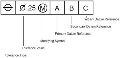
The block can be a single row, as we see in the previous figure, or it can have multiple rows for composite tolerances. The following table lists the common Modifying Symbols that are present in these tolerances.
|
Term |
Symbol |
|
At Maximum Material Condition |
|
|
At Least Material Condition |
|
|
Projected Tolerance Zone |
|
|
Free State |
|
|
Tangent Plane |
|
|
Diameter |
|
|
Spherical Diameter |
|
|
Radius |
|
|
Spherical Radius |
|
|
Controlled Radius |
|
|
Reference |
|
|
Arc Length |
|
|
Statistical Tolerance |
|
|
Between |
|
We will demonstrate how to build these control frames with an example.
CREATING A GTOL CONTROL FRAME
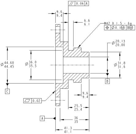
To demonstrate how to create Geometric Tolerances, we will open up the drawing entitled GTOL_Create.drw, which currently looks like the following.

We can see axes, dimensions, a note, and some set datums. We are going to create our first geometric tolerance by going to Insert, Geometric Tolerance, which will bring up the following window.

This window has four main tabs. These are:
· Model Refs – Define the type of tolerance, and specify how it is going to be placed on the drawing. Also allows you to specify which model to use in the case of an assembly. NOTE: Your set datum must be in the model where you want to show it. Therefore, if you have an assembly, you can not create a GTOL for one part, and reference a set datum in another.
· Datum Refs – Specify the datum references.
· Tol Value – Specify the tolerance value.
· Symbols – Add modifying symbols to your frame.
The first tolerance we are going to create will be a Flatness tolerance. Therefore, we will pick on the symbol that corresponds to the flatness. Refer back to the first table to identify which button corresponds to the different tolerances, or move your mouse over the buttons until you see it listed in the tool tip.
Once we pick on the “Flatness” symbol, we will see that the type of reference to select changes from an Edge to Surface, as shown in the next figure.

We will pick on the Select Entity button, and then pick the edge that represents the surface, as shown in the next figure.

When we do this, we now see another portion of our window become active, as shown in the next figure.

The Placement section will specify how the frame is to be placed. If we use the pull-down we can see a variety of methods for placing the control frame on our drawing.

We are going to place our first frame using the With Leader option, which will place a leader from the frame to the model on the view. Once we select this option, we get the following menu.
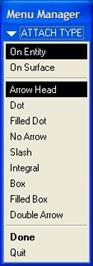
Currently, the default settings indicate that our leader will have an arrow head and will go to an entity, such as an edge, axis or vertex. We will pick the same edge that we picked before for defining the surface that is to get the flatness tolerance. Once you pick on the edge, it will become a bold red. Use the middle mouse button out in the view to place the frame, and you will see the following.

A preview of the frame is now on our drawing view, and it will update as we continue to fill in the frame. We will now click on the Datum Refs tab, which currently looks like the following.

The GTOL frame builder is intelligent. It knows that since we picked a “Flatness” tolerance type, there are no datum references that we can call out. Therefore, it gave us this window. Click on the Tol Value tab to continue. It looks like the following.

Currently, the default tolerance is 0.001. We will change this value to 0.02, and then hit the <ENTER> key on the keyboard. The preview updates.

Within this “Tol Value” tab, we also can define material conditions for the tolerance. We will not be specifying any for this particular tolerance. Therefore, we will click on the Symbols tab to continue. It looks like the following.

In this window, we can see some symbols that are available for this type of tolerance and any references we’ve defined so far. We will not define any additional symbols; therefore click on OK to complete this first tolerance frame. Our drawing view will currently look like the following.

Save the drawing.
GTOL FRAME IN NOTE
The next Geometric Tolerance we will create will be attached to a note containing a dimension. In general, Geometric Tolerances can not be attached to a free note, but they can be created as a free note.
Therefore, go back to Insert, Geometric Tolerance to start a new GTOL. We can see that the window is exactly as we left it for our last tolerance definition. We will pick a Position tolerance this time.
Once we do this, our window will look like the following.

In the Reference field, we can see that Edge is currently selected. If we use the pull-down, we can see other reference types we can select.

We will use the default of Edge, and select the edge shown in the next figure.

You should always try to pick on geometry that the GTOL controls. In this case, we are going to be attaching our GTOL frame to the “M42 X 1.5 – 6g” note, which is currently going to the same edge.
Once we pick the edge, the Placement type we are going to use is Dimension. Remember, we can not attach to a free note, but the “42” in our current note is actually a dimension that was used in the note. Therefore, we can click on the Select Entity button for the Placement filed, and select on this note. When we do, we can see a preview attach itself to the note, as shown in the next figure.

Now, we will go to the Datum Refs tab. It currently looks like the following.
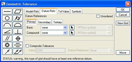
For a positional tolerance, we do have fields that we can define on this tab. In the middle of the window, we see three tabs entitled Primary, Secondary and Tertiary. For this tolerance, we are only going to define one datum reference, therefore we will stay on the “Primary” section.
Since we are not doing a compound tolerance, we will use the Basic row, and use the pull-down to select which datum acts as the primary reference for this tolerance, as shown in the next figure.

We will use B for this reference. Once you select a reference, you have the ability to define material condition for this reference. We will use the pull-down to see a list of possible material conditions.
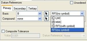
In this case, we will select the MMC (Maximum Material Condition) option. When we do this, our window will now look like the following.

We will now click on the Tol Value tab. For the tolerance value, enter 0.1 in the field provided, and then we will use the Material Condition pull-down at the bottom to specify a material condition for the tolerance itself.
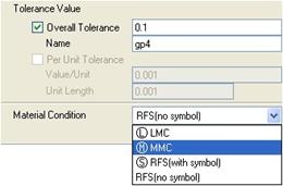
We will select the same material condition (MMC) that we used for the reference. Our window now looks like the following.

Finally, we will click on the Symbols tab, and add a Diameter Symbol to our tolerance field, as shown in the next figure.

Click on OK to complete this tolerance, and our note will now look like the following.

The FRONT view for our drawing now looks like the following.

Save the drawing.
TANGENT LEADER PLACEMENT
The next Geometric Tolerance we will create will use a tangent leader as the placement type. Therefore, go to Insert, Geometric Tolerance once more from the menu bar. This time, select a Parallelism tolerance. For the reference type, make sure Surface is selected, and pick on the following surface in the FRONT view.

When we do this, for the placement field, use the pull-down to select Tangent Leader, as shown in the next figure.
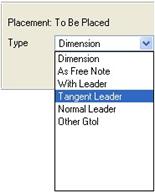
Once we select this, we get the following menu.

Typically, with a Tangent Leader, you use the No Arrow leader type. Therefore, we will select on this option from the menu above, and then pick on the same edge we picked on before. Using the middle mouse button, place the frame above the existing dimensions, as shown in the figure below.

Currently, the definition of the tolerance, datum reference, and material conditions are still left over from the previous tolerance that we defined. Therefore, we will need to go in and edit it to get the following.

For the material condition fields, set it back to RFS (no symbol), which will eliminate the “M” symbol. Also don’t forget to remove the diameter symbol. The FRONT view will look like the following once you complete this tolerance.
Save this drawing.
DIMENSIONS WITH SET DATUMS
We are now going to create a geometric tolerance tied to a dimension that has a set datum attached to it. Create a new geometric tolerance, and pick a Perpendicularity tolerance. For the reference, we are going to pick Surface, and then pick on the same surface that we used for our first Flatness tolerance definition.
Once we pick on this surface, use the Dimension placement type, and pick on the 44.60/44.45 limits dimensions to the left of our FRONT view (the one that currently has the “C” set datum attached to it.
When we pick on this dimension, we can see the GTOL frame attach itself to the dimension, and the set datum attaches itself automatically to the frame, as shown in the next figure.
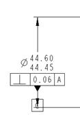
On the tolerance creation window, there is a button called Move, which will allow us to temporarily move the GTOL while we are still defining it. Click on this button and move the tolerance to the following location.

Now we will go in and edit the values and add any material and modifying symbols as necessary to get the final tolerance, as shown in the next figure.

Save and close this drawing. We will come back to it in the exercises for this lesson.
SYMBOL LIBRARIES
There are several libraries of symbols that are available in Pro/ENGINEER and in our company. These are:
· Surface Finish Symbols
· Weld Symbols
· Custom Company Symbols
CUSTOM COMPANY SYMBOLS
In an upcoming lesson, we will learn how to create draft entities in drawing mode – which is the method to define symbols. For now, we will learn how to access already created symbols.
By default, we have a config.pro file that points to the location of our custom symbols. If you have the correct config.pro loaded, then you will always end up in the custom symbol location when you go to insert a symbol.
To demonstrate this, create a brand new drawing. Accept the default name, and the default model that is associated (even if it says None). Use an A size sheet. We are not going to add any views to this drawing.
To access our symbols, go to Insert, Drawing Symbol, Custom, which will bring up the following window.

You can see the location is listed as User Syms in the pull-down field. Out in the main window, you will see a list of defined symbols. Your list may be different depending on the organization.
To demonstrate the symbol window, we will open up the tri_flag.sym symbol. When we open this symbol, we get the following window.

As we move our mouse around the drawing, a preview of the symbol follows the mouse, as shown in the next figure.

Looking back at our Custom Drawing Symbol window, we can see that there are three tabs. The first tab (General) is used to define the symbol, the placement, and the size/rotation/color of the symbol.
For the placement types, you have the same sort of options you have for GTOL frames, and notes. Depending on the symbol definition, you may or may not be able to use leaders. For this symbol, it is most commonly used without leaders, so we will leave the placement type as Free.
For now, we will also leave the height and angle at the default values. If we click on the Grouping tab, we see the following.
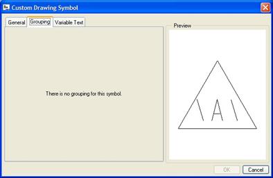
As you can see from this figure, no grouping has been defined for this symbol. Grouping allows you to create different configurations of the same symbol instance. Each defined group can turn on/off draft entities or text in the group definition. We will see this in more detail in the next two symbol types (Weld and Surface Finish).
If we continue on to the next tab, called Variable Text, you can see the following.

When you define a symbol, if you place text in back slashes - \text\, you can create variable text that can be changed each time the symbol is used. Text that is not in back slashes will be read-only in the symbol.
We can see that we have a variable text that currently has a value of A. We will edit this and enter 5. Click anywhere on the drawing to place the symbol, and then click on OK to complete this symbol.
On our drawing, we see the following symbol.

To edit this symbol, you would simply double-click on it to get back to the symbol window.
SURFACE FINISH SYMBOLS
To access surface finish symbols, go to Insert, Drawing Symbol, Custom, which this time brings us back into the surface window, where the last symbol we used is still active. We will click on the Browse button next to the name of the symbol (on the General) tab.
This brings us back into the file open window. In the pull-down field at the top, select System Syms, as shown in the next figure.

This brings us into the following window:
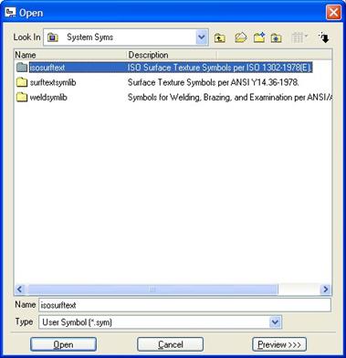
In this window, we can see two different Surface Finish folders, and a weld symbol folder. The first folder is for surface finishes following the ISO 1302-1978(E) standard. The second folder is for surface finishes following the ASME Y14.36-1978 standard.
We will double-click on the ASME Y14 standard folder. This reveals a single surface finish symbol, as shown in the next figure.

We will open this single symbol (surftexture.sym), and we will get the symbol creation window, which looks like the following.
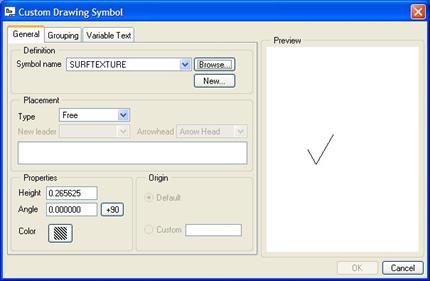
We will leave the defaults alone on the first tab, and go to the Grouping tab. We will see the following options in the group window.
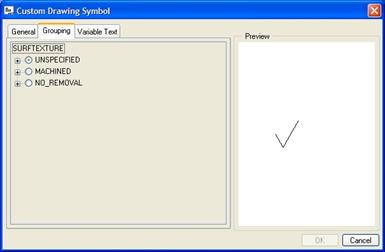
This is a perfect example for using groups. There are hundreds of possible surface finish combinations, and instead of creating hundreds of individual symbols, a single symbol was created that contains all of the possible definitions. By turning on/off certain options, we can get all of the different combinations possible.
At the top level, we can specify whether this is for an Unspecified, Machined, or No-Removal surface. Within each of these options, are further options that can be defined. If we were to expand all three options to see the possible sub-options, our window would look like the following.

We will expand the Unspecified option to see the detail up close.

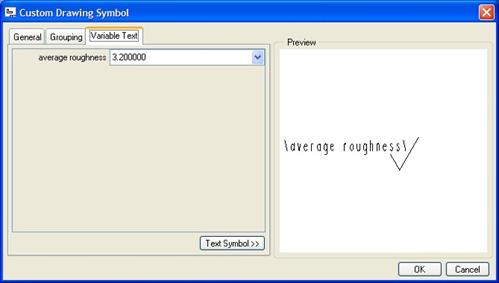
As you check items, and sub-items, it starts to build your custom symbol in the window to the right. We will select the Average Roughness option, as shown in the previous figure, which adds variable text to our symbol.
If we go to the Variable Text tab, we can edit the value for this variable text. In this case, we will enter 3.2 for the average surface roughness, as shown in the next figure.
Clicking out on our drawing gives us our current symbol.

If we had more than one of these surface finish symbols to define, we could go back to the General tab, and click on the New button, which starts a new surface finish symbol, using the current definition as the starting point. Every time we click on the drawing, we place this symbol in its location, and then click on New to add a new one.
Click on OK to complete this symbol.
WELD SYMBOLS
To create a weld symbol, we repeat the process as the last section until we get to the folder where we see the three different system symbol directories. This time, we select the Weldsymlib folder, which gives us the following.

As with the surface finish symbols, there are two standards to choose from for weld symbols: ISO 2553:1992(E) and ANSI/AWS A2.4-93.
We will double-click on the ansi_weld folder, which gives us the following folder options.

These are the first of the different categories for weld symbols. We will double-click on the Simple folder to continue. This brings up the following window:

From this window, we can see a list of individual symbol definitions. We will open up the first one (bevel.sym), which brings up the following symbol create window.
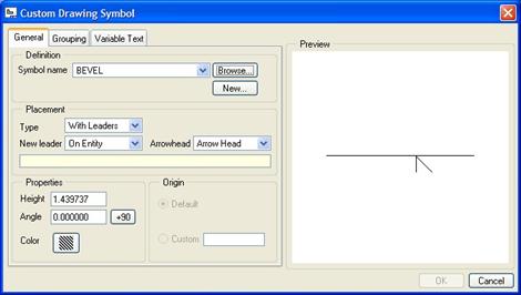
One of the differences in this symbol is that we can use a Free placement type. We will have to pick a location for the leader to go to, but we will come back to that once we have defined the group options. Therefore, click on the Grouping tab, and select the options shown in the following figure.

When we have defined these group options, click on the Variable Text tab, which shows two parameters we can modify based on our selection of options.

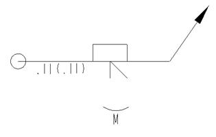
Go ahead and enter any values you want. I will leave the current values for this example. To place this symbol, we need to go back to the General tab. We will leave the Placement Type at With Leaders, but we will change the New Leader value to Free Point, and then click out in the drawing. After you click, you will notice a preview of the symbol with its leader appears.

Drag the symbol to the location you want, and then click on the middle mouse button to finish the drag. Click on OK to complete this symbol. The following figure shows the location where I dragged it.
Close this drawing without saving.
LESSON SUMMARY
Geometric Tolerances can be applied to your drawing in a variety of ways. Be sure you have your set datums, axes and dimensions fully detailed before adding the Geometric Tolerance to make it easier.
Symbols can be created to automate common drafting tasks. In a later lesson, we will learn how to create a basic symbol with some grouping.
EXERCISES
Now, using techniques learned in this lesson, complete the Geometric tolerances on the GTOL_Create.drw drawing, as shown in the next figure.
