Lesson 43

Lesson Objective: In this lesson, we will learn about adding general views, and some basics about the view properties window. We will also learn about the drawing mode toolbar.
DRAWING MODE TOOLBAR
In the System Toolbar, there is a set of icons for drawing mode. These icons look like the following.
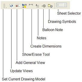
From left to right, these icons do the following:
· Set Current Drawing Model – If you have more than one model associated with the drawing, you can use this tool to make one of the models the current active model. We will talk about this in more detail in a later lesson. You can also get to this functionality through File, Properties, Drawing Models.
· Update Views – Certain changes update in the drawing automatically, while other changes require you to update all of the sheets and all of the views. This icon is used to do this. You can also get to this through View, Update, All Sheets.
· Add General View – This icon lets you add general views to your drawing. You can also get to this through Insert, Drawing View, General from the menu bar.
· Show/Erase Tool – This icon accesses the tool used to show or erase dimensions, axes, reference dimensions, notes, geometric tolerances, set datums, etc. already created in the model. You can also access this tool through View, Show and Erase.
· Create Dimensions – This tool allows you to create driven dimensions in the drawing. These dimensions do not exist in the model, and can not be used to change the model itself. This functionality can also be accessed through Insert, Dimension, New Reference.
· Notes – This tool allows you to create notes on the drawing. You can also access this functionality through Insert, Note.
· Balloon Note – This tool allows you to create balloon notes on the drawing. You can also access this functionality through Insert, Balloon.
· Drawing Symbols – This tool allows you to access your custom symbols library. You can access this functionality through Insert, Drawing Symbol, Custom.
· Sheet Selector – When you have more than one sheet on your drawing, the current sheet is listed in this field. You can use the up/down arrows to go through the sheets. You can access this functionality through View, Go to Sheet.
GENERAL VIEWS
The first view that you add to a drawing is called a General view. It has no pre-defined orientation, scale or style. To demonstrate this functionality, we will go back to the Lesson41a.drw drawing that we started earlier.
Currently, it looks like the following:

Click on the Add General View icon in the system toolbar, and the message window will show the following prompt: “Select CENTER POINT for drawing view.”
We will pick out in the middle of the drawing. Initially, the view appears in the default orientation, as shown in the next figure.

A properties window appears for the view, as shown in the next figure.
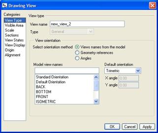
The first thing we will do is select the orientation for the general view. In the main portion of this window, we can see a list of saved views. We will scroll down, and double-click on TOP. When we do this, we can see the view update on the drawing. Click on OK to continue. Our view now looks like the following.
One of the things you might immediately notice about this view is that there are little letters enclosed in squares, with leaders going to triangular bases. These are called Set Datums (or Datum Features in ASME Y14). They are used in conjunction with geometric tolerances. This model has some set datums defined, and they appear on the view when we create it. We can clean these datums up on this view. First, look at the following figure.
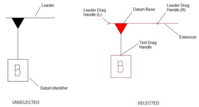
The figure on the left shows the datum feature before we select it. We can see that there are two main components to this datum feature – a leader that identifies which surface/entity the reference is tied to, and the identifier, which gives the label for the datum.
If we pick on this datum feature, it highlights in red, and we can see some little red squares appear (as shown in the figure on the right). The squares on the leader line can be used to move the leader endpoints. The square at the base of the identifier is used to move the text in and out from the base.
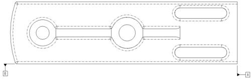
If you place your mouse over the base, you will see a four-arrow symbol that allows you to move the datum identifier along the leader. We will clean up the leader lines so our datums look approximately like the following figure.
We will now go back and look at the view properties window for this general view.
GENERAL VIEW PROPERTIES
When we place our mouse over the drawing view, we can see a light blue dashed rectangle appear. Click once to highlight the box in red. We can now right click and go to Properties which brings up the view properties window. (NOTE: We can also double-click on the view once we see the blue rectangle to get to the properties window).
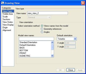
On the left side of this window is a list of Categories that we can select for the particular view. The first category is View Type, which defines type of view, the system name for the view, and the orientation.
We can see that the view type is grayed out (but indicates General). At this time, we have no other views on the drawing from which we could convert this to a different type (like projection, or auxiliary, etc.)
We can also see the default system name for this view is New_View_2. The name can be shown on the drawing for projection views, or for defining templates.
Finally, we can see that we have the ability to re-orient this view using the saved view list, or by picking on a different method for orientation.
Visible Area
The next category down is used to create broken views, partial views, half views, or to add z-direction clipping of the view (like cutting away the part from the point of view of the screen behind a certain planar surface)
This category looks like the following for this general view.

We will come back in a later lesson to see how to create half, partial and broken views. For now, click on the Clip view in Z-direction box, and then pick the following flat surface on the view:
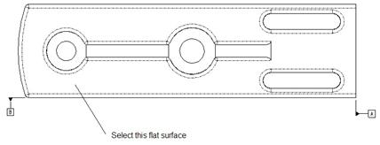
Click on Apply, followed by Close. What do you notice? All of the geometry beyond this flat surface is no longer visible in this view, as we can see in the next figure.

Go back into the properties window, return to the Visible Area category, and uncheck the box. Click on Apply. Now we will continue to the next category.
Scale
When we apply a default view, we have the ability to change its scale with respect to the current drawing scale. If you recall, the current drawing scale is 1:1. This means that as long as we print this drawing on the same paper size as the drawing format or sheet size selected, the views will be at a 1 to 1 scale. A 1” dimension should measure 1” with a ruler.
In Pro/ENGINEER, we don’t scale the model. We always create the 3D models at full scale. We only scale the drawing or drawing views. The Scale category for this drawing view looks like the following:
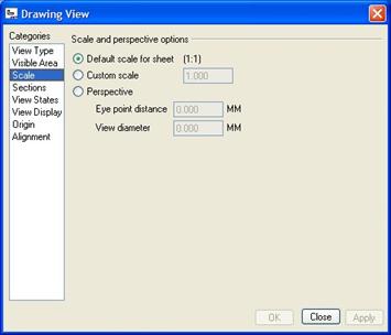
The default option is to keep the view at the current drawing scale. If we wanted the view to have a different scale, we would pick Custom Scale, and enter a value in decimal or fractional format (.5 or ½, for example). NOTE: It is better to scale the drawing if most of the views are going to have to be scaled, and then use this interface to scale selected views differently. You should not scale all general views on the drawing, and leave the drawing view at its original scale.
We can also add perspective to a general view.
Sections
The next category is used to create cross-sectional views, or views of distinct surfaces of the model. It looks like the following for this general view.

Currently, the default option is No Section. If we wanted to add/create a cross-section (planar or offset), we would use the 2D Cross-Section option. We will demonstrate this in an upcoming lesson.
If you want to create a view of a particular surface only (perhaps for calling out special instructions for painting or coating of a surface), you can use the Single part surface option, and then select the surface on the model. NOTE: If you do this, and then decide later that you don’t want this, you will have to delete and re-create the view.
View States
This category is used to define exploded views, simplified representations of assemblies, and mechanism snapshots. It looks like the following.
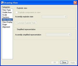
Because this view is of a PART model, and not an assembly model, these options are currently unavailable.
View Display
The next category is used to define the display mode for the drawing and entities on the drawing. It looks like the following.

Currently, this view is in Wireframe display. Tangent edges (like those created by the round features), are currently displayed in Phantom mode (dashed lines).
The hidden line removal for quilts is currently grayed out, because it is not applicable in Wireframe display mode. You can also define how colors, skeleton models, and weldments are displayed on the drawing view. We will change the display style from Wireframe to No Hidden, as shown in the next figure.
![]()
Click on Apply to see the model update. In this particular case, there is no difference for this view.
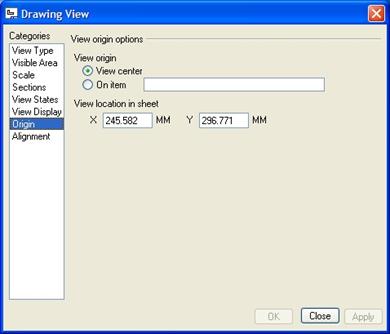
Origin
The next category helps you define the origin of the view. By default, the origin of a drawing view is at the center of the view. We can see a red square at the center of our view to indicate this when we select the view.
If you wanted the origin to be at the corner or other location on a view, you could specify it here, and then you can use the X and Y coordinate locations to define the exact location of a view on the sheet. This category window looks like the next figure.
Alignment
If we had other views on the sheet that came before this general view, we could align this view to one of the views. You might do this to align two general views, or a separate detailed view with its parent.
The alignment category window looks like the following.

You specify whether the alignment is a horizontal or vertical one, and then you pick the references or view origins on the current general view to the other view.
NOTE: You are not converting the view to a different type, only lining it up with another view so they move together. Click on Close to get out of the properties window.
LESSON SUMMARY
The first view in any drawing is a general view. Use the different categories in the properties window to further define the view once it is placed.
EXERCISES
None