Lesson 42

Lesson Objective: In this lesson, we will learn how to create a new drawing, apply a drawing format, and a drawing setup file.
CREATING A NEW DRAWING
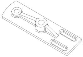
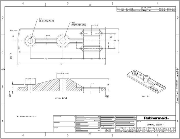
To demonstrate how to create a new drawing, we will start by opening a model that the drawing is going to be created from. Therefore, open up the model called Lesson41a.prt, which looks like the following:
We are going to demonstrate how to create the new drawing file, add the format and drawing setup file. In later lessons, we will learn how to create views, show dimensions, create geometric tolerances, etc.
In this lesson, we are going to start the new drawing, associate the model to it, add a drawing format, and add the drawing setup file in preparation for adding views, dimensions, etc.
We will look at parameters in the model and how they fill in the title blocks, etc.
NEW DRAWING
Before we get started, switch your working directory over to Drawing, located in your ProETrain folder.
We are going to start by going to File, New, and pick on Drawing as the primary object type. For the name, type Lesson41a, which is the exact name of the part file we are working with. NOTE: It is important to use the same name as the primary model in your drawing. The reason for this is due to making a copy of the drawing. If your model and drawing have the same file name, when you perform a SAVE_AS on the part, it makes a copy of the part, and its drawing as well. This will save you from having to re-create the drawing for the copied part.
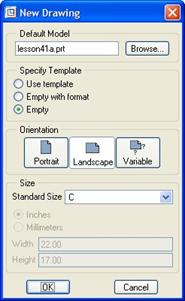
The New window currently looks like the following:
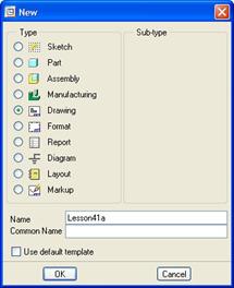
Down at the bottom, you can see a check box labeled Use Default Template. If we were using a company-created template drawing, we want this to be checked. For our training class, we are not going to use template drawings, so we will leave this unchecked.
You can also see that there are no sub-types for drawings. Click on OK to continue. We now see the following window.
The first thing we need to check is the model listed at the top of this window. By default, it uses the last model that was active. Since we just opened our Lesson41a.prt part file, it should be listed.
If this is not the case, or if you have not opened a model recently, click on the Browse button to find the model to use.
Next, we have another chance to specify a template drawing, or to bring the drawing in empty with an associated drawing format, or just empty. The default is Empty, which we will leave.
Next, we can specify the orientation of the drawing. We always want to use Landscape, but it won’t really matter once we apply the actual drawing format, which will replace all settings as they are now. That is why we will leave this default at landscape.
Finally, we have the ability to pick a sheet size to start with. We will pick C to start. Once your window looks like the previous figure, click on OK to continue.
We can now see an empty drawing. There is a rectangular border around the drawing that represents the sheet boundary (“C” in this case). At the bottom of our working window, we can see a summary of the drawing to this point, which looks like the following:
![]()
From this we can see that the overall drawing scale is 1:1, the active model is a Part, and the name of that part is Lesson41A. Finally, we can see that our current sheet size is C. If we needed to change the scale or sheet size, we could double-click on these values in the summary and these would invoke the proper interface to make those changes. For now, we will leave these alone.
ADDING A DRAWING FORMAT
For this lesson, we are going to add a drawing format at this time. Normally, we would add the format once we are ready to release the drawing, and have created and cleaned up our views.
If you recall, we picked an empty “C” size drawing sheet. We are now going to add a format to this sheet. To do this, go to File, Page Setup from the menu bar. This brings up the following window:
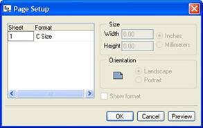
Currently, there is only one sheet, so there is only one row in our window. Had we had multiple sheets, we would see a row for each sheet. We can apply different formats for different sheets. Generally, I would recommend against this. The only thing we will do is have a different format sheet for the first sheet of the drawing and one that is used for the rest of the sheets. This will make more sense in a little later.
Currently, we can see that for sheet one, we have a C Size format applied. This is the generic empty “C” size that we picked. If we click on the word C Size, we can see that it becomes a pull-down field to select from other formats in our library. We can see the following.
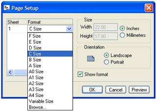
In this list, we can see all of the default PTC sheet sizes for English (A, B, C, D and E) and Metric (A4, A3, A2, A1 and A0). We can also see a choice called Variable Size. We could use this to create a custom sheet size, which would invoke the rest of the options in this window.
The last choice is Browse, which will let us search for a format to use. We will click on Browse, which brings up the following window.

Typically, companies use a configuration file called Config.pro, which defines the location for global standards. The location of company-approved formats is often one of these standards defined. If you have a config.pro file that calls out the location for standard formats, it comes up by default, as shown in the figure above.
For this training class, we will all work off the same formats for consistency, therefore, we will want to click on the folder that brings us into our current working directory (which we selected as the folder called Drawing). The figure above shows the icon to select to get to our working directory. Once we pick on this, we see the following drawing formats to choose from.
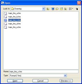
We will pick on the Train_Frm_C format, followed by Open. Our page setup window now lists this format, as shown in the next figure.
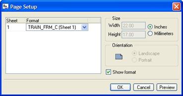
We can see that for sheet one, the current format is TRAIN_FRM_C (Sheet 1). Notice the “Sheet 1” comment at the end. Why is this? In ASME Y14 standards, the first sheet of a drawing has more information than the rest of the sheets (referred to as continuation sheets). Therefore, Pro/ENGINEER formats can contain two sheets. The first sheet of the format is typically applied to the first sheet of a drawing when used. The second sheet of the format is typically applied to the second, third, etc. sheets of a drawing.
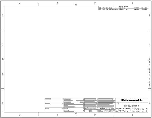
Therefore, our drawing sheet 1 in this example is using the first sheet of the drawing format. When we click on OK to complete this page setup, we can see the drawing format applied to our drawing.
DRAWING SETUP FILES
The Config.pro file that we talked about before governs the behavior of Pro/ENGINEER as a whole, but there is a special file that governs the behavior of drawings. This is called a Drawing Setup File, and has a .dtl extension.
The Drawing Setup File controls the units of the drawing, the text properties, line styles, view display styles, rules for tolerances, etc. We have drawing setup files that follow the ASME Y14 standards in their values for these types of controls. For the purpose of the training class, we have included a copy of these in our current working directory.
By default, Pro/ENGINEER has its own drawing setup files. The Config.pro file that we use calls out a company standard setup file as the default, but this may be different for each division, so we want to get in the habit of retrieving one into our current drawing before we add views, notes, dimensions, etc. Failure to add the drawing setup file before the views may result in some re-work.
To access the drawing setup file and its options, go to File, Properties. This brings up the following menu manager.
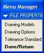
In this menu, we can see three different options. The first (Drawing Models) is used to access the current drawing models in the drawing. The last (Tolerance Standard) is used to control tolerance mode.
We will pick Drawing Options, which brings up the following window.
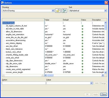
At the top, there is a File Open icon. Pick on this, and you will be brought into your working directory. We will stop a minute to talk about something.
If you were to look at the units of our model, they are in Millimeters. If you recall, we chose a C size sheet for our drawing. It might seem logical to select a drawing setup file that is tied completely to the sheet being used. This would be an incorrect assumption. Why?
The rules governing metric drawings are completely different than those governing English drawings. For example, dimensions in millimeters are not allowed to have trailing zeros (zeros after the decimal point). English dimensions are not allowed to have leading zeros (zeros before the decimal point).
The drawing setup files have the correct settings to control this. If we were to pick a drawing setup file in English units, then our drawing would have the rules for English dimensions applied to metric dimensions. This could throw off Tolerancing, etc.
We do need to understand the sheet size that we are using to make sure our text heights, arrow lengths, line weights, etc. are appropriate for reading the values when printed, so we can not completely ignore the “C” size sheet.
Therefore, we need to pick a drawing setup file for millimeter dimensions that corresponds to an approximate “C” size sheet. So, what are the equivalents for metric and English paper sizes? The following table shows the equivalents.
|
English Paper Sizes (inches) |
Metric Paper Sizes (millimeters) |
|
A (8.5 x 11) |
A4 (210 x 297) ~ (8.23” x 11.7”) |
|
B (11 x 17) |
A3 (297 x 420) ~ (11.7” x 16.54”) |
|
C (17 x 22) |
A2 (420 x 594) ~ (16.54” x 23.39”) |
|
D (22 x 34) |
A1 (594 x 841) ~ (23.39” x 33.11”) |
|
E (34 x 44) |
A0 (841 x 1189) ~ (33.11” x 46.81”) |
Even though there is a clear difference in size from English to metric sheet sizes, we can see that the equivalent for a “C” size is an A2 size. Therefore, the drawing setup file that we will pick will be the a2a3a4.dtl drawing setup file (located in our current “Drawing” working directory. Our window looks like the following:

Click on Open once you have selected this drawing setup file. The Options window now lists the settings that correspond to this file, as shown in the next figure.
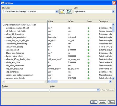
We are not going to go through all of these settings. Suffice it to say that they do follow ASME standards, so we can be confident in the outcome of our drawings using these files. Click on OK to apply the settings and close out of the window.
Save the drawing.
LESSON SUMMARY
When creating a new drawing, be sure to name it the same as the primary model used in the drawing. Before adding any views to a drawing, add the drawing setup file that corresponds to the model units and sheet size being used.
Drawing formats are added to the sheets. Formats should be applied once you know how big your sheet size will need to be to accommodate the different views, their dimensions, notes, symbols, etc.
EXERCISES
None