Lesson 40

Lesson Objective: In this lesson, we will learn about Flexible Components, Merge and Cut-Out, and Repeat Component Placement.

FLEXIBLE COMPONENTS
There are some models that change each time you use them. Typically, there is a “steady-state” for these components, but when they are used, dimensionally they are altered. A perfect example of such a component is a compression spring. In its steady-state, it has a certain length. When used, the length is either compressed or stretched out.
If you recall from Lesson 35 – Family Tables, we can create a family of “like” components. Many users might consider using Family tables to create different spring models, but the problem is two-fold:
1) There can be an unlimited number of possible lengths that can be achieved with the spring, so you would have to almost create a new instance for each usage.
2) Family table instances are unique parts, each with its own unique name. When used in an assembly in multiple configurations, this approach would create as many individual components. A Bill of Material would not be very accurate unless you specifically altered each component’s parameters to be identical.
The advantage of using flexible components is that the new dimensional data for that model is stored with the assembly, so the original part is not altered, and yet we can capture an infinite number of lengths for the component when used. Each instance is the original model, so the quantity in a BOM is accurate.
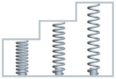
To demonstrate this concept, we will switch our working directory over to the Flex_Asm folder. Open up the Flexible_Spring.asm model. It consists of a rim part and three instances of the same spring, as shown in the figure below.
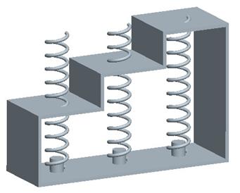
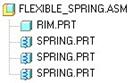
The model tree confirms the fact that all three spring models are the same part.
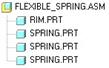
What we want to be able to do is have the length of the three springs be different for each one so they fit in the space provided, which is shown in the next figure.
Preparation of Spring
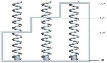
For the spring to work properly, we have a relation that calculates the pitch based on the length of the spring (between TOP and DTM2) divided by 10 coils. Therefore, if we change the length, the spring compresses or extends.
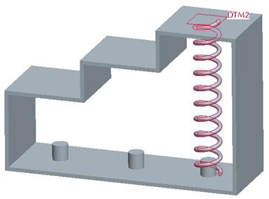
If we turn on datum planes, we can see DTM2 for each of the springs. DTM2 controls the length of the spring, but unfortunately, based on the way the spring was created does not go from one extreme to the other. The following figure shows the actual length of the spring relative to the bottom of the spring as it would rest in our part.
We can see DTM1 at the bottom of the spring. Each spring, when assembled, lines up the DTM1 plane with the bottom inside of the rim part so the spring is resting on the bottom without any interference.
The length of the spring in its steady state is 10.000”, the distance from TOP to DTM2. The remaining distance is 0.25” – therefore, we need to subtract ¼” from the actual distance we want to cover to modify the length of the spring.
Therefore, from left to right, the new length of the spring would be 4.5, 7.0 and 9.5 respectively.
Make Flexible
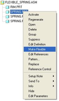
Now that we got that out of the way, we are ready to adjust each of the springs. We will start with the first one in the model tree. Right click on the spring and select Make Flexible, as shown in the next figure.
This brings up the following window.
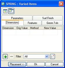
By default, we are placed into the Dimensional variation tab. In the working window, we can see the component highlighted in red, as shown below.
We need to pick on the feature that contains the dimension to vary. In this case we will pick on the DTM2 datum plane. This will show the 10.000 dimension. Pick on this dimension, followed by the middle mouse button, and it will be added into our window, as shown below.
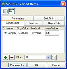
When adding dimensions, the default method for entering the new value is based on data entry. We simply pick in the field and type in the new value (9.5 in this case). There are other ways to calculate the new value if you don’t already know it. If we use the pull-down field Method, we see other options. One of these, for example, allows you to measure the distance between two entities.
We will click on OK to complete this change, and our model updates. We will repeat this process for the other two springs, entering 7.0 for the second one, and 4.5 for the third. When complete, our assembly will look like the following.
Our model tree has a little “Spring” icon on top of the blue cube indicating that the components are flexible, as shown in the next figure.
Save and close this assembly.
Aside from controlling dimensions, the flexible component can also vary parameter values, feature regeneration status (keep in mind suppressing a feature will suppress all of its children), surface finish and geometric tolerance data.
MERGE
A merge operation is performed in the context of an assembly. It takes one or more parts and merges them into a single, specified part. To demonstrate this functionality, open up the model entitled Assy_Merge.asm. It will look like the following:
We will take a moment to interrogate this assembly. It is made up of four components. The first three contain solid features. The fourth (Stand_Alone_D) contains only the default datum information. We will come back to this part a little later.
If we go to View, View Manager and click on the Explode tab, we can see a default explode state. Double-clicking on this shows us the following.

Right click on the default explode state and select Unexplode View. Now, click on the Xsec tab, and we can see two cross-section views listed, A and B. Double click on A and you will see the following.
Double-click on B to see the following.
We can clearly see the boundaries of the individual components in the two cross-sectional views. We will come back to the cross-section views once we perform the merge operation to show you the result.
Example 1 – Merge into Existing Component w/Solid Geometry
In this example, we will merge Components “B” and “C” into Component “A”. Therefore, go to Edit, Component Operations, which will bring up the following menu manager.
We will click on Merge. When we do this, the message bar prompts us with the following: “Select parts to perform MERGE process to.” For future reference, we will refer to the model we select as the TARGET. We will pick on the Stand_Alone_A component (either directly, or in the model tree). Click on the middle mouse button to accept this selection.
We are now prompted to “Select reference parts for MERGE process.” For future reference, we will refer to these models as REFERENCE MODELS. We will pick Stand_Alone_B and Stand_Alone_C using the Ctrl key to pick multiple items. Once both are selected, click on the middle mouse button to accept these selections.
The menu manager now looks like the following.

This menu has two sections. The first deals with how the new merged model behaves with respect to the original model. The options are:
· Reference – The TARGET model will be dependent on the REFERENCE model. A change to the REFERENCE model will update the TARGET model.
· Copy – The TARGET model will be independent of the REFERENCE model. A change to the REFERENCE model will not update the TARGET model.
The second section is used to copy datums from the REFERENCE model to the TARGET model. The options are:
· No Datums – Only solid volume will get merged into the new part. Typically, if you are merging into a part that already contains default datum planes, you don’t need to duplicate the planes.
· Copy Datums – Datums will be copied along with the solid volume into the new part. You may wish to use this if you are merging into an empty part (without any datum features).
We will accept the default options of Reference and No Datums, and click on Done to continue. In the message bar, we get the following prompt:
![]()
Before we explain this, we ought to define one additional piece of information. If the placement constraints of the REFERENCE MODEL are tied completely to the TARGET model, then we will consider this to be a LOCAL REFERENCE. If the placement constraints of the REFERENCE MODEL are tied to any other reference other than a TARGET reference (i.e. – other part in the assembly, or assembly datum plane, for example), then we will consider this an EXTERNAL REFERENCE.
When you select the option Reference in the menu manager, and your model is a LOCAL REFERENCE, then you will get this prompt. If your model is an EXTERNAL REFERENCE, then you will not get this prompt. If you used Copy instead of Reference, then you will not get this prompt.
Okay – so what is this prompt asking? Since the model in question (Stand_Alone_B) is being merged using the Reference option, and it is a LOCAL REFERENCE to the TARGET part (Stand_Alone_A), then answering Yes to this prompt will allow an update to the placement of this part to update the TARGET as well. For example, if we used a MATE OFFSET to locate Component “B” to “A”, and later changed the offset distance, the TARGET part would update with the new position of component “B”.
If we answer No, then we can change the original placement of the REFERENCE part and the TARGET will not update. We will answer Yes to this prompt. When we do this, we get the next prompt:
![]()
Answering Yes to this will remove STAND_ALONE_B from the assembly, leaving only three components. Since we answered Yes to the previous prompt, then we should answer No to this, otherwise, we will never be able to re-define the placement of this component. Therefore, we will answer No.
At this point in time, we are now asked to deal with Stand_Alone_C, and we see the same menu as before.
Now, this component is not a LOCAL REFERNCE. It is an EXTERNAL REFERENCE, because it is assembled to Stand_Alone_B, and not to the TARGET (Stand_Alone_A). Therefore, if we pick either Reference or Copy, we will not get the first prompt that we got before.
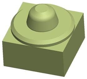
We will accept the defaults for this menu, and pick Done. We are not prompted at all for this component. On our model (with shading on) we can see that there is now overlapping geometry, as shown in the next figure.
Go ahead and hide Stand_Alone_B and Stand_Alone_C in the model tree, and you will see that our Stand_Alone_A component now has the volume of B and C added to it, as shown in the next figure.

Try looking at your cross sections, and you will see that this is truly one solid volume made up of three separate components. Now, open up Stand_Alone_C, and add a 1.0” round to the edge shown below.
Switch back over to your assembly, and regenerate it. You can see (even with the part hidden) that the round has transferred to the TARGET part. This is because of the Reference option that we picked.
What is Happening at the Part Level?
If we open up the Stand_Alone_A part, and look at the model tree, we can see the following.

We can see two merge features at the bottom of the tree. If you click on the first one, the geometry representing Stand_Alone_B highlights. if you pick on the second one, the geometry representing Stand_Alone_C highlights.
If we wanted to return to the original “A” part, we would have to delete the two merge features. This is something important to keep in mind. The TARGET part will be altered when you merge. If we were trying to create a temporary model for analysis or other reason, we might want to consider using an empty part (such as our Stand_Alone_D) model.
To demonstrate this, go ahead and delete the two merge features from this part, return to the assembly, and unhide the “B” and “C” components.
We are going to create a new merge by using Edit, Component Operations, Merge. For the TARGET part, select Stand_Alone_D from the model tree. Click on the middle mouse button to accept this.
Next, for the REFERENCE PARTS, select “A”, “B” and “C” components form the model tree. Click on the middle mouse button to accept these. For all three, select Reference and No Datums from the menu manager when it comes up. As you do this, you will notice new geometry appearing on the model embedded into the three existing components.
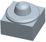
When done, hide the first three components, and you will see the following.
Copy
Now, we will demonstrate the difference between Reference and Copy. Up to now, we have referenced the original models in the TARGET. Now, we will open up the Stand_Alone_D model, delete the three merge features that we just created, and return to our assembly. Unhide all three components.
This time, when you perform the merge as we just did, use Copy instead of Reference. Hide the three components again in the assembly, and you still see the same result. The difference is when you open up the Stand_Alone_D part.
What do you notice? Well, the first thing you might have noticed is that when you picked the Copy option, the option to include or exclude datums was not available. In a Copy datums are automatically copied.
The second thing you might notice is that in the part (Stand_Alone_D), the model tree now contains all of the features for all three components, in addition to the default datums it had. The model tree is shown in the next figure.
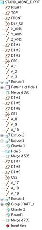
All of these features are now completely independent of the models that created them. An update to Stand_Alone_A, for example, will not update this model. We can, however make changes now to any of these features in this part.
The other thing we might want to do is go through and edit references for the added datum planes to get them to use the default planes for this model. For example, if we look at the top of the model tree, we can see that we have our default model datum planes (RIGHT, TOP and FRONT).
The next set of datum planes (DTM1, DTM2 and DTM3) correspond to the features merged from Stand_Alone_A. We can edit the references for DTM1, and re-route all features to RIGHT. Doing the same for DTM2 and DTM3 would allow us to delete these planes from this model to reduce clutter.
Again, using an empty part is ideal if you don’t want to alter the original models being merged. Save and close this part, and the assembly.
CUT-OUT
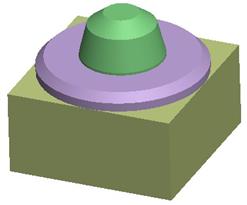
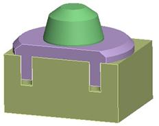
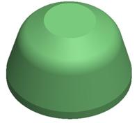
A Cut-Out is exactly the same as the merge in almost all respects. The only difference is that it removes material from the TARGET instead of adding material to it. To demonstrate this, open up the assembly entitled Assy_Cut-Out.asm. It looks like the following.
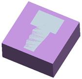
This assembly consists of two components (Stand_Alone_E and Stand_Alone_F). The “F” component sits within the “E” component. The purpose of this is to extract the volume of “F” from “E”. A good example of using this is to create a die model. Another reason you might use this is for dual-material parts, or parts that are over molded. You can create a volume, assemble another volume into it, and then subtract the interfering volume.
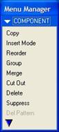
We will go to Edit, Component Operations and we see the same menu as before.
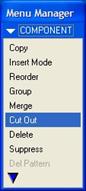
This time, we will select the Cut Out command, as shown above. When we do this, we get the following prompt in the message bar: “Select parts to perform CUT OUT process to”. This is the TARGET part, as we remember from the merge operation. We will select the Stand_Alone_E part from the model tree.
Click on the middle mouse button to accept our choice. Now the message bar reads: “Select reference parts for CUT OUT process”. We will pick Stand_Alone_F from the model tree, followed by the middle mouse button.
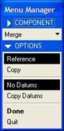
We see a somewhat familiar menu as before.

The biggest difference is the ability to include or exclude datums. The same rules still apply for Reference and Copy as the merge operation. We will pick Reference, followed by Done. When we do this, we get the same prompt: “Support associative placement for the feature?”
Remember, this prompt comes up if you select Reference and the REFERENCE MODEL (“F”) is tied to the TARGET (“E”) in terms of placement (which it is). We will answer Yes to this prompt.
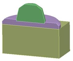
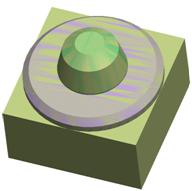
Another difference between merge and cut-out is the fact that we do not get another prompt at this point. Instead, our cut-out is complete. If we hide component “F” in our model tree, we can see the following.
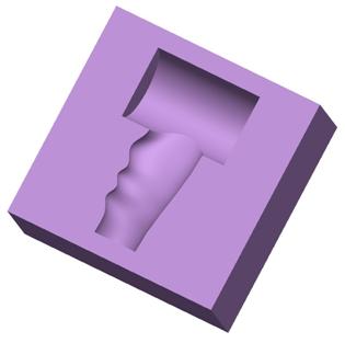
In our part file for Stand_Alone_E, we see the following model tree.

Save and close this part and assembly.
REPEAT COMPONENT PLACEMENT
When you are assembling a component multiple times into an assembly, you can repeat the placement process to save time. A great example would be to assemble in a fastener where a pattern is not readily available to take advantage of.
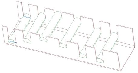
To demonstrate this, we will open up the assembly called Repeat.asm. It looks like the following:
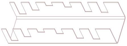
It currently consists of a single part called Repeat_Base. This part has notches cut out along the length. Each notch is the same width, but is spaced differently, and at different heights. The notches are not patterned. We are going to assemble in a bar across each of these notches.
Since the notches are not patterned, we can’t simply assemble the bar on the lead notch, and then reference pattern it. We also don’t want to have to go through the complete assembly placement commands for each one independently. Therefore, we will learn about a tool that will save time in a case like this.
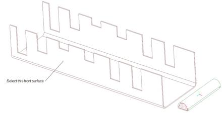
We have to start by assembling one of the bars. Therefore, pick on the assemble component icon, and select the Repeat_Arm part. When it shows up in the window, we will start picking references, starting with the following on the arm.

For the assembly reference, select the following surface on the far left side of the base.

This should create a Mate placement constraint with a “Coincident” type applied. Now, back on our arm, select the next surface.
Then, on the base, pick the following surface.
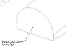
This should create a second Mate “Coincident” constraint. Finally, pick the last surface on the arm, as indicated below.

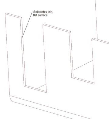
On the base, select the following thin surface at the far left of the part.
We will be prompted for an offset distance. Type in 0.0, and then change the type to “Coincident” in the placement window. Our Component Placement window will look like the following when done. Click OK to complete the placement.
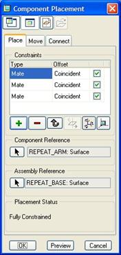
On the assembly, we can see the first arm assembled.

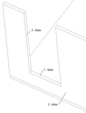
Now, to be able to use the repeat command, we need to remember what assembly references we picked, and in what order. If you recall, we picked the following surfaces in the order indicated in the figure.
Remember this, because we’ll come back to this. To access the repeat command, first select the component to repeat. Therefore, we will pick on the Repeat_Arm component in the model tree so it highlights in red in the working window.
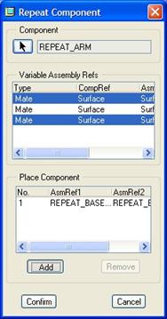
Next, go to Edit, Repeat from the menu bar. This will bring up the following window.
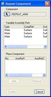
At the top of this window, we can see the three placement constraints used to assemble this arm, and in the order in which they were picked starting from the top to the bottom of the list. These correspond to the 1-Mate, 2-Mate and 3-Mate two figures back.
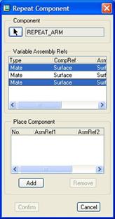
What we need to do is pick which references are different for each new instance of the arm we add. If we remember the three references, the second one was the large flat front surface, which all of the notches share as a common reference. The first and third mate commands, however, used surfaces that were unique to each notch. Therefore, the only references that will be unique for each bar placement will be the first and last ones.
We will pick both of these in this window, as shown in the next figure.
If you imagine what would be the first and second reference for each additional arm being placed, it would be the following.
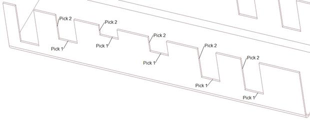
“Pick 1” represents the surface that we would pick for the first mate, while “Pick 2” represents the surface we would pick for the last mate.
Now, we will pick on the Add button. When we do this, the reference used for the first Mate command highlights on the model, and we are asked to pick the equivalent. This is where we pick the first “Pick 1” in the previous figure.
Then, the second reference highlights, and we will pick on the first “Pick 2” reference from the previous figure. All of a sudden, an arm appears in the second notch, as shown in the next figure.

In the Repeat window, we can see one instance added to the list at the bottom.
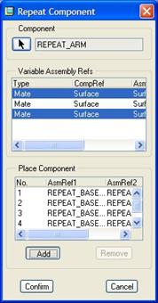
The first reference is highlighted again, so we go back to picking the “Pick 1” surface for the next notch, followed by the “Pick 2” reference for that same notch. Keep picking the “Pick 1” and “Pick 2” references for each additional notch until you see an arm in each one. At this time, our model looks like the following.
Our Repeat window now lists all of the instances in the bottom.
If we don’t have any more to add, we will click on the Confirm button, and our placements will be complete.
As you can see, you can save a lot of time by just picking the assembly references that are unique to place each arm. Save and close this assembly.
LESSON SUMMARY
Flexible components are great when you need to use the same model, but vary it each time. Merge and Cut-Out operations add/remove material from a TARGET part by using one or more REFERNCE PARTS. Just be careful to select the options that will work for your needs.
Finally, use the Repeat command to bring in more than one of the same objects where tedious repetition would otherwise be required.
EXERCISES
None