Lesson 38

Lesson Objective: In this lesson, we will continue to learn about assemblies by a top-down design approach.
TOP-DOWN DESIGN
The idea behind Top-Down design is to try to build in intelligence between the fit, form and function of parts that reside in an assembly. You try to capture this fit, form and function into the assembly first, and then pass the appropriate information down to the part level so that a change made at the assembly level or to one component in the assembly can drive updates to the rest of the critical parts.
In this method, many of the components are created in the assembly, instead of being assembled into the assembly.
SKELETON MODELS
The best way to capture fit, form and function for the assembly is to create a special kind of component called a Skeleton Model. A Skeleton model is similar to a regular part, but it is treated specially in the assembly. For example, a skeleton model is automatically excluded from the Bill of Material, where if you just created a regular part and used it like a skeleton, it would still be reported.
There are also restrictions that can be placed on regular parts that skeleton models are exempt from, or get special rights to deal with. For example, you can make it so you are not allowed to copy surfaces from a regular part to another regular part, but you can still pass surfaces from the skeleton model to a regular part. In defining such restrictions, you avoid creating parent-child relationships between individual part files, making the model more robust.
To demonstrate this principal, we will first create a new assembly file called Stacker. Be sure to use a Design sub-type for this assembly, just as we did for the last lesson. Also, once you have the assembly started, be sure to turn on the features in the model tree.
CREATE COMPONENT - SKELETON
On the feature toolbar, we have another assembly icon that looks like the following.
![]()
This is the Create Component icon. When we pick on it, we get the following window.
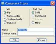
We can see in this window that we have the ability to create parts, sub-assemblies, skeleton models, and bulk items. We will talk about bulk items in a later lesson. For now, select Skeleton Model. The default name for skeleton models is the name of the assembly appended with “_SKEL”, as shown in the next figure.
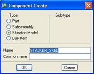
We can also see that there are no sub-types for a skeleton model. I recommend leaving the default name alone, and click on OK to continue. We get the next window.
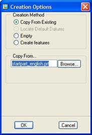
In this window, we are asked to specify how the model will be created. We want to always use the Copy from Existing option, and browse to get to our start part that we want to use. In this case, the startpart_english is already selected, so we will click on OK to continue.
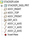
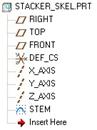
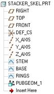
The skeleton model has now been added to our assembly, as we can see in the following figure.
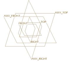
In our model tree, we can see that the skeleton model has been placed at the top of the list, even before assembly features. This is one of the hints that lets us know that it is a skeleton model versus a regular part, which would have showed up at the end of the list.
We will now open up the skeleton model separately to add datum geometry to this model. If we right-click on this component in the model tree, we will see the following options.
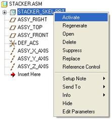
Select the Open option, and the skeleton model will open up in a new window.
SKELETON GEOMETRY
Skeleton models typically only contain datum or surface geometry. You should only try to capture enough information to drive the models where they interface. I have seen individuals create almost an entire assembly and all of its components in the skeleton so no changes have to be made at the part level, but this is overkill, and will over-complicate the model. Therefore, the less you can place in the skeleton but still maintain the complex relationships between parts, the better.
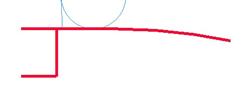
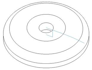
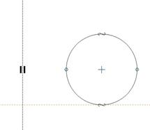
In this example, we will start by creating a sketch feature (Lesson 5). Use the FRONT datum plane as the sketching plane, and face the RIGHT datum plane towards the Right. We will then create the following sketch.
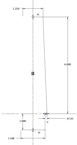
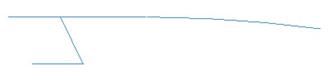
NOTE: There is a vertical centerline in this sketch that allows for the diameter dimensions at the top and bottom. When we complete this sketch feature, we have the first curve in our skeleton model, as shown in the next figure.

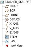
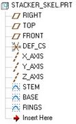
In our model tree, we will right click on this sketch feature and select Rename, and rename the sketch to STEM, as shown in the next figure.
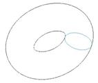
You are not required to rename the feature, but I recommend it so you know what it controls if you need to make a change later. Now, we are going to create a second sketch feature using the same sketching plane and horizontal/vertical reference. Our sketch will look like the following.

When completed, the skeleton model now looks like the following.
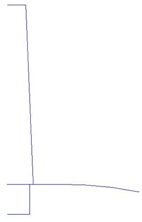
We will rename this second sketch feature to BASE, as shown in the next figure.
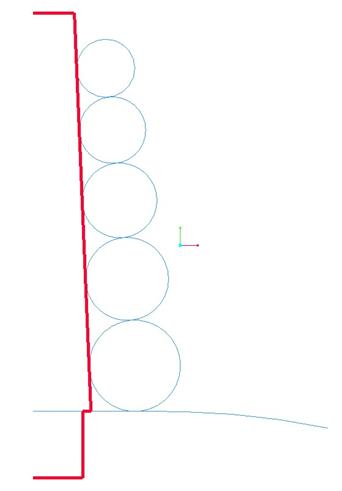
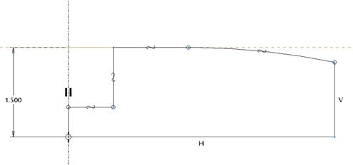
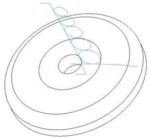
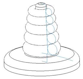
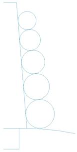
We have one more sketch feature for this skeleton model, which will be on the same sketching plane and H/V reference, and looks like the following figure.
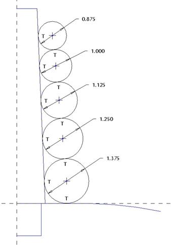
The completed skeleton model will look like the following.
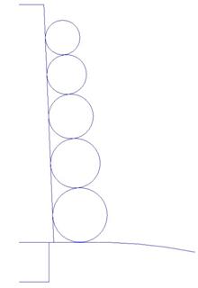
We will rename this last sketch feature to RINGS, as we can see in the figure below.
Save and close the skeleton model, and then return to the assembly. We can see the curves in our assembly, because the skeleton model is already assembled. Save the assembly.
CREATE ADDITIONAL COMPONENTS
The next thing we are going to do is create parts in the assembly for each of the individual components that will ultimately make up this assembly. We are going to have seven components in this assembly, as shown in the following product structure.
STACKER
· Base
· Stem
· Blue_Ring
· Green_Ring
· Yellow_Ring
· Orange_Ring
· Red_Ring
Base Component
Therefore, return to the assembly file, and then click on the Create Component icon again. This time, select Part, Solid, and enter Base for the name, as shown in the next figure.
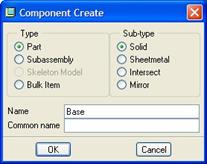
Click on OK, and in the next window, be sure that you are copying from an existing start part (in this case Startpart_english.prt). We can also see that when we are creating a part object, we see a slightly different window than what we saw when creating a skeleton model.

At the bottom of the window, we have an option to leave the component unplaced. The reason you might do this is if you were simply trying to capture the product structure at this time, but then you wanted to come back later and locate the component once you have geometry.
This might be especially true if you have mechanism connections that are going to exist. Even if you don’t check this option, you can always come in later and edit the definition of the component, and re-define the placement constraints. Therefore, we will leave it unchecked whenever we create a component in the context of an assembly.
Click on OK to continue, and we now have our Component Placement window. We will click on the Default Placement icon to allow the part to be fixed to the assembly datum planes. Click on OK once you select the Default Placement icon.
In the working window, you may not be able to distinguish the new part, because we only have default datum planes, but in the Model Tree, we can see the Base component added, as shown in the next figure.
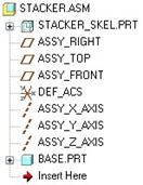
We will repeat this same process to create the remaining six components in the order in which they are listed in the product structure on the previous page. The model tree, when complete, will look like the following.
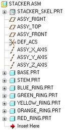
Save this assembly once you have added the rest of the components.
PUBLISH GEOMETRY
When you want to pass data from one model to another in top-down design, you use a tool called Copy Geometry. Copy Geometry is done in the component where you want to copy the geometry to (called the Target). The Source of the geometry comes from the Skeleton Model, assembly or other component.
In our case, we are going to copy geometry from the skeleton model into each of the seven individually created components.
Preparing the Skeleton
If you recall, we have three sketch features in our skeleton model. At this time, we don’t have to do anything. When we use the copy geometry command within one of the components, we will be able to selectively pick the curve segments we want to pass.
Left the way it is, there is no guarantee that the user that is responsible for creating the individual component will grab just enough references into his/her model. Too few, and they won’t have enough information to define the connection between the part and the skeleton. Too many, and it just wastes features and disk space in the component.
Pro/ENGINEER has a tool that allows you to pre-define groups of data to pass from one model to the other. This tool is called Publish Geometry. It allows you to define all of the necessary items (curves, surfaces, points, planes, axes, etc.) and group them logically so when the user goes to copy the geometry, they only have to pick one item and get all of the necessary entities.
For our example, it might be a bit overkill to define the individual publish geometry features, but we will do it for practice. For large, complicated models, you will want to use publish geometry features. It will become more clear as we go through an example.
The limitation of a publish geometry feature is that it can only be created from entities that exist in the model where the publish geometry is being created. With regular copy geometry features, you can copy external references into your model. But, by working with skeleton models, we are better positioned to have all of the entities within the skeleton model.
Base Publish Geometry
Therefore, go back and open the skeleton model. From the menu bar, select Insert, Shared Data, Publish Geometry. This will bring up the following window.
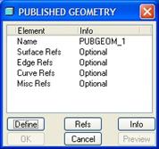
As you can see, we can optionally define surface references, edge references, curve references, or a variety of miscellaneous references (Axes, points, csys, etc.). This is nice, because we can publish all of the entities for the base that we need, regardless of what type of entity they are.
We only have curves in our skeleton model, therefore, we will pick on the Curve Refs item, followed by the Define button. We will get the following menu.
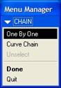
We can select entire chains of curves, or individual curve segments using the default option of One By One. We will keep the default option, and then select the following four segments using the Ctrl key.
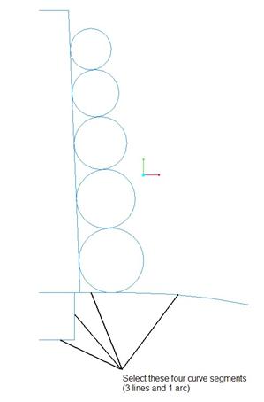
When all four are selected, they will be highlighted in a bold red, as shown in the next figure.
Click on the middle mouse button to accept this selection, and then click on Done in the menu manager. In the Published Geometry window, click on OK. In our Model Tree, we can see the current publish geometry feature.
We will want to rename this feature to BASE_PG. NOTE: When you rename features in the model tree, they have to have unique names. Therefore, we append the “_PG” at the end so we can tell that this is the Publish Geometry feature for the base.

Stem Publish Geometry
For the stem, we will repeat this same process, but select the following entities.
Don’t forget the small horizontal curve segment. You may need to use the Right mouse button to query select until you see this segment highlight.
Rename the finished feature to STEM_PG, as shown in the next figure.

Ring Publish Geometry
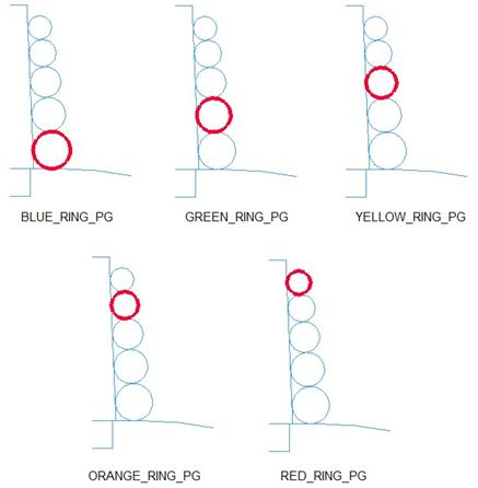
Repeat this same process to create the publish geometry features for the individual rings, starting with Blue and ending at the Red ring. The following figure shows which curve references to pick for each publish geometry feature.
The completed model tree for the skeleton model will look like the following.
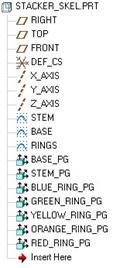
Again, using publish geometry for our simple example may be overkill, but you should get in the habit of using publish geometry to organize the data you want to pass from the skeleton to the individual parts.
The nice thing to point out is that each publish geometry is not a copy of the entities, and therefore doesn’t take up a lot of regeneration time or disk space. It is merely an organizational tool.
Save and close the skeleton model once you are done creating all of the individual publish geometry features.
COPY GEOMETRY
Now that we have created the individual components in our assembly, and we have defined all of the publish geometry in our skeleton, we are ready to pass the information from the skeleton down into the individual part files.
To do this, we will go back to the assembly file.
Base
In the Model Tree for the assembly, right click on the Base component, and select Activate. This makes the active working model the base, even though we are currently in the top-level assembly. This is critical, because if we just went back to the base model itself, the skeleton would not be there to pick from, and we would be forced to work in multiple windows. By activating the part in the assembly, we can work in a single window. The trade-off is with the amount of clutter you have on the screen for large assemblies. This is where simplified reps or component displays, or merely hiding components will help organize your working environment.
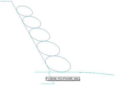
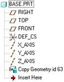
We know the base is active, because the model tree has a green pinwheel symbol on the base part, and in the working window, we can see text indicating the active object, as shown in the next figure.
![]()
With the Base part active, we will go to Insert, Shared Data, Copy Geometry from the menu bar. This brings up the following window.
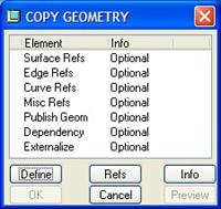
From this window, we can see that we have the ability to define surfaces, edges, curves, etc. just like we did when we created the publish geometry. We could have selected Curve Refs here, and picked the same references in the skeleton model that we picked before. This would by-pass the publish geometry feature, and for our simple model would have worked just as well.
You can also see a Publish Geom line item in this window. We will click on this, followed by Define. This brings up the following menu manager.
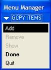
Out on our working window, we can move our mouse over one of the entities that made up the base publish geometry, and it will highlight the entire publish geometry for the base, as shown in the next figure.
We can now pick this. We could have also expanded the features of the skeleton model in our model tree and picked the publish geometry for the feature directly. Once you select the BASE_PG publish geometry feature, click on the middle mouse button to accept it, followed by Done in the menu manager.
Click on OK in the Copy Geometry window, and the copy of the curves should be complete. To verify this, open up the Base.prt part file by itself, and you should see only the curve entities that were part of the publish geometry feature, as shown in the next figure.
We will now activate the rest of the components (one-by-one), and use the Insert, Shared Data, Copy Geometry, Publish Geom tool to grab the appropriate publish geometry feature and place it in the active part.
Save the assembly when you have finished copying the geometry into each part. Open each one to verify that you have the correct data.
FINISH COMPONENTS
Now, we can open up the individual components and add any necessary solid/surface features to create our models. We will go through each one individually now.
Base
Open up the base part, which should have the existing datum curves copied from the skeleton. In our model tree, we can see a copy geometry feature listed, as shown in the next figure.
We will now create a revolve feature. Use the FRONT datum plane as a sketching plane, and face the RIGHT datum plane towards the Right. Inside the sketch, use the Copy Edge tool to grab the existing curves from our copy geometry feature, and trim away the left side of the top-most horizontal line. Complete the sketch with three additional line entities, as shown in the next figure.
Don’t forget a vertical centerline as the axis of revolution. Revolve 360 degrees to get our first protrusion.
Finally, add a 0.75” round to the outside top edge, as shown in the next figure.
Save and close this part. When we return to the assembly, we can see the base part geometry.
Stem
Open up the stem model. Create a revolve feature using the FRONT datum plane for our sketching plane, and face the RIGHT datum plane to the Right. Use the Copy Edge tool to get all of the existing curves from the copy geometry feature, and then close the left side with a line. Don’t forget the vertical centerline for the axis of revolution. Our sketch should look like the following.
Revolve this feature 360 degrees to create the first protrusion, and then add a 0.25” round on the top edge of this model to produce the final stem part, as shown in the following figure.
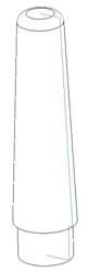
Save and close the stem part.
Blue Ring
Open up the Blue_Ring model. Repeat the same process to create a revolved protrusion. Don’t forget to add a vertical centerline on the existing vertical sketcher reference, as shown in the next figure.
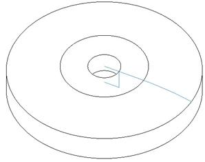
The completed ring will look like the following.
Save and close this part.
Green, Yellow, Orange and Red Rings
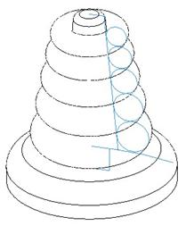
Repeat the same process that we did for the blue ring to create the remainder of the rings. When you are done, and have saved each ring model, return to the assembly, and it will now look like the following.
MAKING CHANGES
From the previous figure, we can see that the diameter of the base is too large. We can also see that the angle on the stacking rings is not quite big enough.
With traditional bottom-up design, we would have to modify every single component. With our approach to top-down design, we only have to modify the skeleton model to accomplish this change.
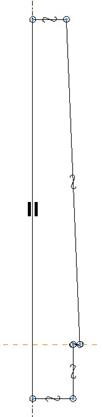
Therefore, go back to the skeleton model, and edit the stem sketch feature. Change the length of the small horizontal line from 0.125” to 0.375”. Next, edit the base sketch feature, and change the length of the horizontal line from 2.0” to 1.0”. Regenerate the skeleton model, and we should now see the following profile.
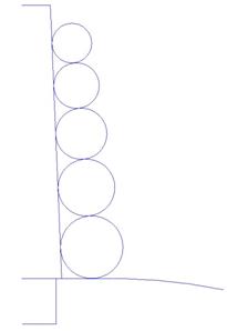
BEFORE AFTER
Go back to the assembly, and regenerate it. The final stacker assembly looks like the following.
Save and close this assembly. We will come back to it in a later lesson.
LESSON SUMMARY
Top-Down design is an approach that passes critical fit, form and function information from the top-level assembly down into the individual components/sub-assemblies. By using Skeleton Models with published geometry, you can make changes to the entire assembly by controlling the skeleton model.
EXERCISES
None.