Lesson 37

Lesson Objective: In this lesson, we will get started with assemblies by demonstrating bottom-up design. The primary focus for this lesson will be to learn how to assemble in existing components into an assembly.
BOTTOM-UP DESIGN
If you recall from Lesson 1 – Pro/ENGINEER Basic Elements, we learned that one approach to assembly design is to start by modeling individual parts, and then start to construct assemblies.
As we create sub-assemblies, we can then assemble these into higher level assemblies. This lesson will go through the steps to assemble components.
CREATING A NEW ASSEMBLY
We will get started by switching our working directory to the Machine_Vise folder. Next, we will go to File, New and when the New window opens, we want to select Assembly in the first column. The second column will list possible assembly sub-types, as shown in the next figure.
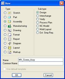
For most assembly mode usage, we will stick with a Design assembly. Many of the other ones on this list are specific for manufacturing.
We will give this assembly a name of MV_Screw_Assy, as shown in the previous figure, and then click on OK to continue to the next window, which looks like the next figure.
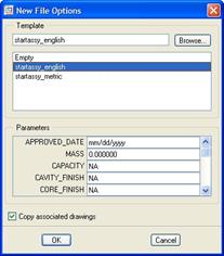
In this example, we will select the Startassy_English assembly because our units are English. You can use whatever template assembly your division uses, just be consistent with your units.
Just like Part mode, we can enter parameter values for the assembly file in this window as well. Click on OK to finish the definition of the assembly.
Assuming that your datum planes are visible, you should now see the following in your working window.

There are three default datum planes, called ASSY_FRONT, ASSY_TOP and ASSY_RIGHT, which are similar to the default part datums, but named with the prefix of ASSY_ to be able to quickly identify assembly datum planes from part datums.
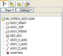
In the Model Tree, we currently only see the name of the assembly, as shown in the next figure.

By default, only part mode shows feature definition in the Model Tree. To see features in assembly mode, we must go to the top of the Model Tree, and pick on the Settings button, which expands to give us the following options.
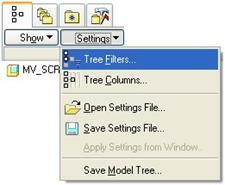
We will pick on the first option (Tree Filters), which brings up the following window.
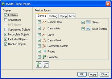
In the right column on this window, we can see a list of different entities that are displayed or can be displayed. Check the box next to Features, and then click on OK. We should now be able to see the default datum features in the assembly.
We are now ready to start building our assembly.
ASSEMBLE COMPONENTS
On the Feature Toolbar, we can see an icon that looks like the following.
![]()
This is the Assemble Component icon. We will click on this and get the following window.

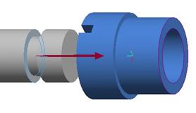
We are asked to select the component to assemble into the current assembly. We will pick on the 07_MV_Vise_Screw part, followed by Open. When we do this, the component shows up on the assembly in the working window, as shown in the following figure.

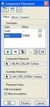
The component comes into the window in a default orientation, and location. To the right of our screen, we have a Component Placement window, which looks like the following figure.
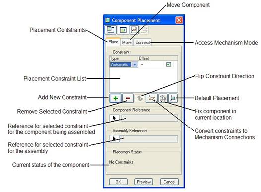
The purpose of this placement window is to allow you to pick on geometry from the component as well as geometry from the assembly and define a relationship between those entities.
Typically, the first component in a bottom-up design assembly is fixed to the assembly (can not move with respect to the assembly), and therefore we use the Default Placement icon to locate our first component.
When we pick on this icon, the three default datum planes of the part align with their corresponding default datum planes in the assembly, as indicated below:
FRONT (component) aligns with ASSY_FRONT (assembly)
TOP (component) aligns with ASSY_TOP (assembly)
RIGHT (component) aligns with ASSY_RIGHT (assembly)
Go ahead and pick on the Default Placement icon, and you will see that the status in the bottom of our window now lists Fully Constrained. We are done placing our first component.
PLACEMENT CONSTRAINTS
If you recall, when we first got into the placement window for a new component, the current constraint was listed as Automatic. It was awaiting entity selection to determine automatically which of the pre-defined constraints made the most sense. I would recommend starting off with Automatic and then adjust the constraints accordingly. In this section we will look at the pre-defined constraints that can be assumed or selected directly.
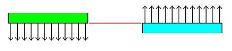
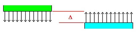
Mate
A mate takes two surfaces and points their normals towards each other and lines up both surfaces, as shown in the next figure.
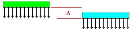
Mate Offset
This is the same as a Mate except that the distance between the surfaces can be less than or greater than zero.
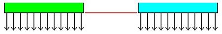
Align
An Align takes two surfaces and points their normals in the same direction and lines up both surfaces, as shown in the next figure.
Align Offset
This is the same as an Align except that the distance between the surfaces can be less than or greater than zero.
Orient (Parallel)
This is similar to an Align offset, except that you don’t specify the distance between the surfaces.

Insert (Coaxial)
An insert takes two cylindrical surfaces and lines up their axes, as shown in the next figure.
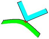
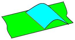
Tangent
A Tangent constraint takes two cylindrical surfaces, or a planar and cylindrical surface and makes them tangent to each other, as shown in the next figure.
Point on Surface
Places a datum point or vertex on a surface, as shown in the following figure.
Edge on Surface
Places a straight edge on a cylindrical or planar surface, as shown in the next figure.
APPLYING CONSTRAINTS UPON ASSEMBLY
To show these constraints, we will continue to assemble components into the MV_Screw_Assy. Therefore, click on the Assemble Component icon, and when the Open window appears, select the 08_MV_Collar component.
When the Component Placement window appears, select the following two entities:

The order doesn’t matter, because it knows that the 07_MV_Vise_Screw component is now part of the assembly, and the 08_MV_Collar is the component part. When we pick both cylindrical surfaces, the axes line up as shown in the next figure.

In our Component Placement window, we can see that it automatically assumed an Insert constraint for this first selection of entities, as shown in the following figure.

We can also see that the status is only Partially Constrained, and we are prompted to create a second constraint in the constraint list window. Therefore, we will now pick on the following two entities.

When we select both flat surfaces, we see a magenta arrow on the part, as shown in the next figure.
In the message bar, we get the following prompt: “Offset (ins) in indicated direction:” Since our component surface was relatively far away from the assembly surface selected, it assumed we wanted an offset constraint. Since we picked two surfaces that were facing in the same direction, it automatically assumed an Align Offset.
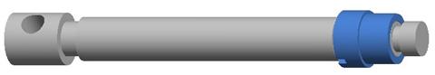
We will enter a value of 0.0 in the message bar, and hit the enter key. When we do this, the blue component will snap over to the following location.

If we look at our placement window, we can see that it is Fully Defined, but there is an option to allow assumptions, and this option is currently checked, as shown in the next figure.
In reality, there is still a rotational degree of freedom open for this component, but that may not be critical in our design, so we can allow the system to fix this rotational degree of freedom for us. If we were to uncheck the “Allow Assumptions” box, we would have to define additional placement constraints to fix this rotational degree of freedom.
Also, if you look up at the constraint list, we can see the last Align constraint that was created. In the Offset column, we can see our entered value of 0.0000. We could leave this the way it is, and it would remain aligned, but if we want to be certain that both surfaces always line up, we can use the pull-down field to change the option to Coincident, as shown in the next figure.
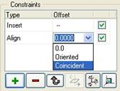
We will do this for our component so we are guaranteed that the placement stays at an Align. If we wanted the flexibility to move the component along the axis, we would have left it as an Align Offset.
Our assembly currently looks like the following.
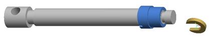
We will now assemble the last component for this particular assembly. Therefore, click on the assemble component icon and select the 09_MV_Special_Key. Initially, it comes into the assembly at the following location.
We will start defining our first constraint using the following cylindrical surfaces.

This will create an Insert constraint for us, and line up the axis of the component and assembly. Now, we will finish off this component by picking the following two planar surfaces.
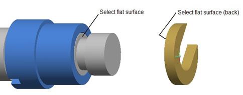
NOTE: We are selecting the back flat surface of the key (the one that we can not directly see in this figure). When we do this, we again get an assumption of an “Offset” condition, and we will enter 0.0 for the offset value.
A Mate Offset constraint is created, and we can now change the Offset column to indicate Coincident, as shown in the next figure.

We can also see that we are allowing it to fix the rotational degree of freedom on this key, which is okay for this component. We will click on OK to complete this component placement, and our assembly model will now look like the following.

Save and close this assembly.
LESSON SUMMARY
For Bottom-Up design, we start by creating an assembly, and bring in components one-by-one. The first component is typically fixed by using the Default Placement constraint. For the rest of the assembled components, we will select an entity on the component and an entity on the assembly, and let Pro/E assume the constraint we want. We can then adjust the constraint as necessary to finalize the placement.
EXERCISES
Create another assembly called Machine_Vise in the same working directory we’ve been working in for this lesson. Begin assembling components starting with 01_MV_Base to create the top-level assembly. Be sure to assemble in the sub-assembly that we created in this lesson (MV_Screw_Assy) instead of assembling the individual 07, 08 and 09 components. The final assembly will look like the following:
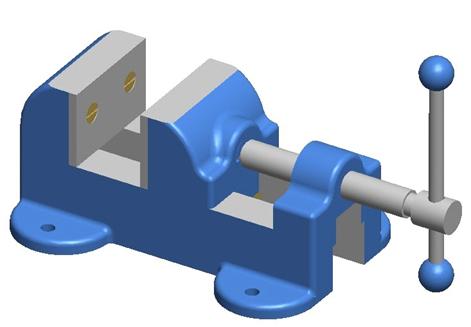
An exploded view of this assembly is shown on the next page for reference in determining how some of the components are assembled.
