Lesson 34

Lesson Objective: In this lesson, we will learn about Parameters and Relations.
USAGE OF PARAMETERS & RELATIONS
Parameters are attributes that exist in the model. These attributes can be used to search on in PDM/PLM systems, and are most commonly used to fill in drawing title blocks automatically. Parameters can also be used to drive dimensional information in relations.
Relations are mathematical expressions that help you control your model. If you recall from the very first lesson, we talked about design intent and parametric modeling. Relations can be used to ensure that your model will react to change in a predictable manner. For example, suppose you always need your width of your block to be half the length. Instead of modifying two dimensions every time your length changes, you can write a relation that will automatically govern the width dimension.
PARAMETERS
To access parameters, go to Tools, Parameters from the menu bar.
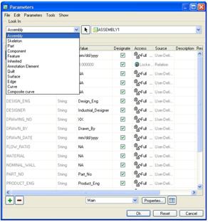
To demonstrate this, we will open up the Assembly1 assembly that we saw in the last lesson. Once open, go to Tools, Parameters. We will get the following window appear.

The main portion of this window lists the current parameters and their values and properties in table format. You can edit many of the property cells directly in this table.
To add a parameter, use the green “+” button at the bottom, and then fill in the information. To remove a parameter, select it in the table, and then use the red “-“ button.
Along the bottom, there is a pull-down field and two buttons. The pull-down field allows you to look at the reported and alternate mass property parameters. The following figure shows the Alternate Mass Properties.

The following window shows the Reported Mass Properties.

These are system parameters that are derived from mass property calculations.
Switching over to another part
Currently, we are looking at the parameters defined in the assembly file. To view the parameters from a different model, or to look at component parameters, etc., we would use the pull-down field in the upper left of the model, as shown in the next figure.
We will select on Part, and then we are instantly placed into the working window to select the part from the model of which we wish to view the parameters. We will pick on one of the screws to access Component3’s parameters. The window now looks like the following.
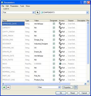
We can see the type as Part, and then name COMPONENT3 listed at the top now.
Parameter Properties
To view all of the properties in a single window for a selected parameter, use the Properties button in the lower right corner of the window. This would bring up the following window (shown for the APPROVED_DATE) parameter.
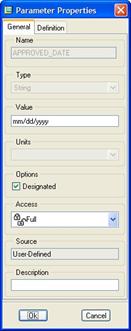
You can edit the data in this window as well.
Customizing the table
The last icon in the lower right corner is used to customize the table display for this window. When you click on this icon, it brings up the following.

You can remove columns, reorder them, and change their size.
RELATIONS
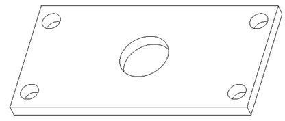
Relations are accessed in the Menu Bar using Tools, Relations. To demonstrate this, we will open up the Plate3 model that we worked with a while ago. It currently looks like the following.
Dimension Symbol Editing
Before we add relations to this block, we should rename the dimension symbol for any dimension that is going into the relation so it makes more sense when viewing the relation later.
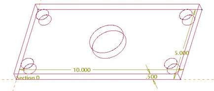
For example the outer shape of the plate is currently a 10”W x 5”D x 0.5”H rectangular block. The dimension symbols for this are: d4 x d3 x d2. Unless you are very familiar with this model, you would not know which one of these is the height or the depth or the width. Therefore, it makes more sense to rename these to the following:
|
Current Symbol |
New Symbol |
|
D4 |
Width |
|
D3 |
Depth |
|
D2 |
Height |
To do this, we will first go to the model tree and select the first Extrude feature. Once selected, hold down the right mouse button and select Edit. The dimensions for this block will appear on the model, as shown in the next figure.
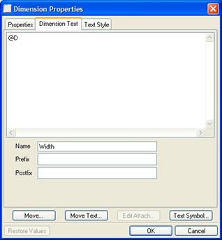
Single click on the 10.000 dimension (Width) so it highlights in red, and then right click and select Properties. This brings up the following window.

This is the Dimension Properties window, which can be used to change tolerances, edit the text, change text style, change dimension type (basic, inspection, etc.), and change dimension symbol.
We are going to go to the second tab, entitled Dimension Text, and then edit the Name field value from d4 to Width, as shown in the next figure.
Click on OK, and then repeat this for the other two dimensions. Be sure to rename the 0.5 dimension to Height (from d2), and the 5.0 dimension to Depth (from d3). We are also going to rename the hole dimensions as shown in the next figure.

Once all of your dimension symbols are renamed, we will create some relations so all we have to modify is the width of the block and everything will update.
Go to Tools, Relations, and you will see the following window.

There is a default relation to calculate the MASS parameter based on a mass property calculation result. We will start a new line at the bottom, and then start to enter our relations. We are going to enter the following.
Depth=Width/2
Height=Depth/10
These two relations will govern the size of the plate itself, always making the depth half the width, and the height 1/10th the size of the depth. Now, we will enter relations governing the X-Locations of the holes.
X1_Location=Width/10
X2_Location=X1_Location
X3_Location=Width-X1_Location
X4_Location=X3_Location
X5_Location=Width/2
This sets all of the small holes equally away from their closest edge, at a distance 1/10th the size of the width. The larger hole in the middle is placed at the halfway point along the width. Now we will enter the Y-Locations of the holes.
Y1_Location=X1_Location
Y2_Location=Depth-Y1_Location
Y3_Location=Y2_Location
Y4_Location=Y1_Location
Y5_Location=Depth/2
This makes the small holes equally away from their closest edge, at a distance equal to the X-Location distance. The larger hole in the middle is placed at the halfway point along the Depth. Our final entries will govern the diameter of the holes.
Dia1=X1_Location*.75
Dia2=Dia1
Dia3=Dia1
Dia4=Dia1
Dia5=Dia1*2
This makes the diameters of the small holes ¾ the size of the X-Location distance. The larger hole is twice as large as the smaller holes.
The relations window will look like the following figure when complete.

Had we not remembered the dimension names, we could have picked a feature from the model, and its dimensions would have showed up on the screen, as shown for the extrude feature.

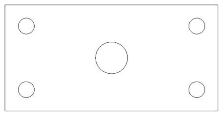
The icons at the top of the relations window provide some additional functionality for testing the relation, reporting values, etc. We will click on OK and then regenerate the model to see the change. Our model now looks like the following figure.
Save and close this model.
LESSON SUMMARY
Use Parameters and Relations to capture design intent and model attribute information. Remember to always rename dimension symbols that you wish to use in relations so that individuals reading the relations later have an idea of what you are trying to do with them.
EXERCISES
Open up the Draft1 part that we worked on earlier. If you recalll, it has a pattern of ribs around the inside. Currently, there are 5 ribs equally spaced at 72 degrees.
We are going to create a relation for this rib pattern that, based on the number of ribs specified, keeps the ribs evenly spaced around the center axis. Test your relation with a rib count of 10, as shown below.
