Lesson 33

Lesson Objective: In this lesson, we will learn about Layers.

LAYER USAGE
Layers are used to organize information in the model. Typically, layers are used to group specific types of datum entities, such as planes, axes, curves, points, etc. Layers can be shown or hidden to help organize and clean up your working environment.
Layers are not like AutoCAD in the sense that they are controlled by colors, or affect printing of certain model entities, although in drawing mode, layers can be used to turn off entities that will then not print.
WORKING WITH LAYERS
The Layers tool is located on the System Toolbar, and looks like the following.
![]()
Hide Layer:
To demonstrate layers in Wildfire 2.0, we will open up the Assembly1 assembly. It will look like the following.

We will be learning about Assembly mode in a later lesson. For now, the Navigator shows the Model Tree. If we click on the Layers tool, the Model Tree is replaced by the Layers interface, which looks like the following for this model.

Most of the layer functionality is carried out with the right mouse button. For example, turn on the visibility of datum planes. From the following figure, we can see how jumbled our model looks with all of the datum planes turned on.

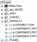
In the Navigator, we can see a layer called _Defaults, which contains all of the default datum planes, datum axes and datum coordinate system. We will click on the “+” box to the left of the name _Defaults to expand it.
Once expanded, there are four models listed under this layer – the assembly itself, and the three UNIQUE components that make up the assembly.
We will use the Ctrl key to select Component1, Component2 and Component3, and then hold down the right mouse button over any one of them.
In the RMB menu, select Hide, as shown in the next figure.

Gray shaded squares appear around the icon for these three
components, and when you click on the refresh button ( ![]() ), you will only see the default datum
planes from the assembly, as well as any planes that are on the _PLANES
layer.
), you will only see the default datum
planes from the assembly, as well as any planes that are on the _PLANES
layer.

We will now turn off the datum curve that resides in the Component3 model. Therefore, we go to the _Curves layer and expand it to see the single component that has this layer.
![]()
We will right click on that component and use the Hide command again. Refresh the model to see that the blue curve is no longer visible.
Save Status
To have the layer status changed for all components affected, you must first hold down the right mouse button over the Layers name in the navigator, and select Save Status, as shown in the next figure.
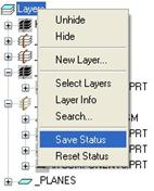
Then, you would save the assembly, which will save all changed components. Be careful, because in Pro/INTRALINK a “Save Status” will be treated as a modified object, and will need to be checked back in once you save.
To return to the last SAVED status, you would click on Reset Status.
Hide All Layers
To hide all layers, you would right click on the word Layers and select Hide. This will gray out all layers, as shown in the next figure.

If you do this, use the Reset Status to undo this so we are back to our last status save (which only hid the _Defaults layer in the three components and the _Curves layer in the component3 model.
Creating a New Layer
To create a new layer, right click on the word Layers, and select New Layer, as shown in the following figure.

This will bring up the following window.

The first thing we want to do is to give this layer a name. We will call it FASTENERS, as shown in the next figure.
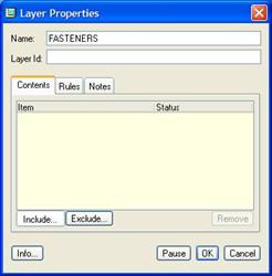
Now it is time to start adding items.
Down at the lower portion of this window, we see two buttons: Include and Exclude. The default is Include, which means that anything we pick will be included in this layer, and subject to the status of the layer. Exclude is used to exempt added items from being subject to the status of the layer, but include them in the layer so we can change their status at a later time.
The Remove button is used to completely take an item (whether included or excluded) off the layer permanently.
We will keep the default of Include, and select the four screws, as shown in the next figure.

As we pick on the component, it will become added in our list with a green “+” in the status column, indicating that it is included, as shown in the following figure.

Once you are done adding items to this layer, click on OK to complete the layer, and it will show up in the navigator.

Now we could hide this layer, and all the screws on the assembly will disappear with the refresh button.
Layer Properties
To get back into a layer definition to add/remove/exclude items, right mouse click on the selected layer, and pick the Layer Properties command, as shown in the next figure.

Once inside, we will click on the Exclude button, and select the last two components in the list. The green “+” status turns into a red “-“ status, as shown below.
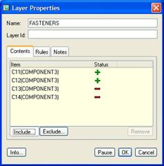
If we had hidden this layer, these last two components would now be unhidden, even though the first two are still hidden. We will click on Cancel to undo this change.
Remove Items
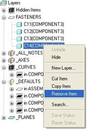
To remove an item from a layer, you could go to the Layer Properties, select on the item in the list, and then click on the Remove button. The other way would be to expand the layer itself in the navigator, as shown for the FASTENERS layer.

We will remove the last component in the layer (C14). Select this component, and then hold down the right mouse button over it and select Remove Item, as shown in the next figure.
When you do this, you will get a confirmation, as shown below.

Click on Yes to remove this item from the layer. Now, if we were to hide this layer, one of the four screws is not going to be hidden. If we go back to the Layer Properties for this layer, we can see that it is no longer listed.

Changing the displayed component’s layers:
Currently, we have been looking at all of the layers for the assembly and any of its components. If we wanted to just look at the layers for Component3, we would use the pull-down field at the top of our navigator to change over to this component, as shown in the next figure.

Now, we can see and manipulate just the layers that exist in this component.
Moving items from one layer to another
To move an item from one layer to another, you can cut and paste the item. To demonstrate this, we will create a new layer for cross-section planes, and then move the XSEC_A_PLANE from the _Planes layer to this new layer.
Create New Layer XSEC_DTMS.
First, we will right click over the word Layers, and use the New Layer option. When the window appears, enter XSEC_DTMS for the name, but don’t include any items. If you include the existing plane, it will now be in two different layers.
The following figure shows us our new layer properties window.

Click on OK to get out of the properties. Now, we will expand the _PLANES layer to see the plane we want to move.
![]()
We will right click on the datum plane and select Cut Item, as shown in the next figure.

When we do this, it disappears from the navigator. We will now right click on the XSEC_DTMS layer and select Paste Item, as shown in the next figure.

A “+” box appears next to the layer, and if we expand it, we can see the item now in this layer.
![]()
Now, we could go back and delete the _Planes layer, since it is now empty.
LESSON SUMMARY
The layer functionality is completely contained within the navigator, and works off of right mouse button commands (which are also available in the three tabs at the top of the navigator).
Be sure to save your layer status before saving your assembly or part files.
EXERCISES
None