Lesson 28

Lesson Objective: In this lesson, we will learn about the Offset Tool.

OFFSET TOOL USAGE
The offset tool is a very versatile tool. It can be used to create a new quilt surface by offsetting an existing solid or quilt surface. It can also be used to replace a solid surface with quilt surface.
Another use for this tool is to create an emboss on a solid or quilt surface by a defined shape. The last use of this tool that we will demonstrate is the ability to offset curves.
USING THE OFFSET TOOL
The Offset tool is located on the feature toolbar, and looks like the following:
![]()
We will devote a separate section to each of the offset types.
SURFACE OFFSET
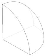
The first type of offset we will demonstrate is one where either a solid surface or an existing quilt is used to create a new offset quilt. This is also known as a standard offset. To demonstrate this, we will open up the part called Offset_Standard. It looks like the following.
We will start by selecting the outside solid surface of this part, as shown in the next figure.
Next, we will click on the Offset tool. A preview of our new surface will appear on the model, as shown in the next figure.

We can use the yellow arrow to flip the offset direction. We will leave it going to the outside. The dashboard for this standard offset looks like the following.
![]()
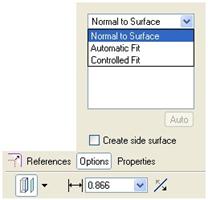
The References panel lists the surfaces selected to offset. The Options panel shows us some additional options for the creation method of this offset, as shown below.
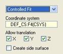
If we were to select the Controlled Fit option, then we would see the following additional items to specify.
We will leave it at the Normal to Surface option, and then click on the Create Side Surface check box. This adds surfaces to the sides of our offset surface, as shown in the following figure.
Go ahead and uncheck this box to remove the side surfaces. In our dashboard, we have another pull-down that defines the type of offset feature we are creating. By default, the Standard offset is selected. The different types are:

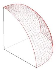
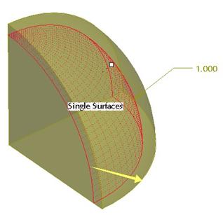
We will leave the type at Standard, change the offset distance to 1.0, and then click on the green check mark to complete this first offset feature. Our model now has a quilt surface as shown in the next figure.
EXPAND OFFSET
Solid Surface Expand
Working with the same model (Offset_Standard), we will use Edit Definition to go back into our offset feature. Once you are back at the preview, change the offset type to Expand. This changes the surface offset into a solid offset, because our surface was solid to begin with.
The preview of this solid expand offset looks like the following.
When we click on the green check mark to complete this change, our model now looks like the following.
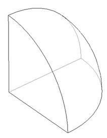
If we take the length of the edge of this part (from the center), we can see that it is 1.0” longer than it was before this offset feature. Close this model.
Surface Expand – Sketched Region
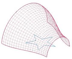
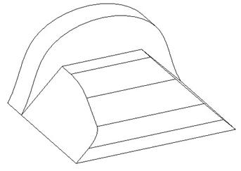
The expand feature also doubles as a Tweak Offset (for both solids and surfaces). We will demonstrate this using the Offset_Expand model, which initially looks like the following.

This model consists of a surface quilt (boundary blend surface) and a sketched star on the TOP datum plane. We are going to offset the quilt within the star to make almost a punch out on the original surface.
Therefore, we will begin by picking the surface quilt, as shown below.
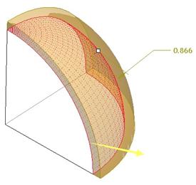
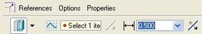
Once this surface is selected, click on the offset tool. Change the offset dimension to 0.5, and our preview currently looks like the standard offset, as shown in the next figure.
Now, we will change the offset type to Expand. When we do this, the preview disappears, and the dashboard now includes an area where you will define a sketch, as shown below.
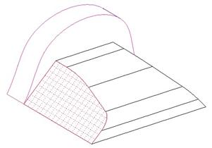
If you don’t have a pre-defined sketch feature, you can right click out in the model and select Define Internal Sketch. We, however, are going to pick the star-shaped sketch. When we do this, we will see the following.

If you rotate this model, you will see that the only offset area is within the star shape itself. It also automatically creates side surfaces. A FRONT view looks like the following.
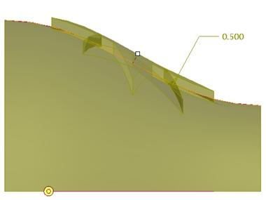
We can see that the sides of this offset are going straight up and down. This is due to the fact that our offset is being defined as Normal to Sketch. We can see this if we open up the Options panel again.
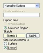
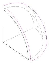
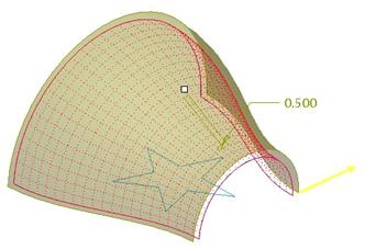
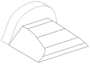
We will change the option to be normal to Surface, and our preview will change to look like the following.

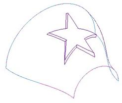
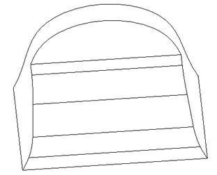
Click on the green check mark to complete this offset expand feature. Our model now looks like the following figure.

You could have done this same thing if the model were completely solid instead of surface quilts.
WITH DRAFT
The next type we will show will use the same model that we just worked on (Offset_Expand).
Start by using Edit Definition to go back into the offset feature again. We will change our type from Expand to With Draft. A new dimension will appear on the model, and our dashboard will look like the following.
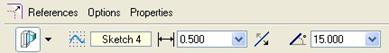
Initially, the draft angle will be 0.000 degrees. Change this to 15.000, as shown above, and then our preview will update to show draft along the offset.
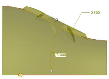
This is really useful, because it makes the draft hinge the bottom of the offset feature where it intersects the original selected quilt/solid surface. You also have the ability to add rounds, but I don’t recommend this, because you have no control over the radius for the round.
Click on the green check mark to complete this change, and our model now looks like the following.
REPLACE SURFACE
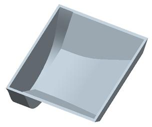
The next type of offset is used as a “Tweak Replace”. To do this, we must have a solid surface to replace, and a quilt that acts as the replacement surface. Therefore, we will demonstrate this with the Offset_Replace model, which looks like the next figure.
This model is shelled out, as we can see from a bottom view.
The model tree for this model looks like the following.

Before we create our offset feature, we will roll the model back before the shell. To do this, drag the red arrow in the model tree up until it is just before the shell, and then let go. The shell will go away temporarily, and the screen will indicate that we are in insert mode. The model tree will look like the following figure.

We are almost ready to create our offset replace feature. If you recall, we must have a surface quilt to use as a replacement surface. We want to replace the larger angled surfaces with the taller swoopy surface. Therefore, we will start by picking the following surface.

With this surface selected, use Crtl-C top copy it, and then Ctrl-V to paste it. This brings us into the surface copy mode, and we will click on the green check mark to finish the surface copy. We can now see a surface quilt on the model.
Now that we have our replacement quilt, we will pick on the first of the two solid surfaces to replace, as shown in the next figure.
We will click on the Offset tool, and we can initially see a standard offset, as shown below.
Change the offset type from Standard to Replace. When we do this, we can see the following dashboard.
![]()
We are prompted to select the quilt that acts as the replacement surface. We will pick on our newly copied surface. When we do this, our preview now looks like the following.

Before we finish this first replace surface command, we will go to the Options panel, and check the box to keep the replacement quilt, as shown below.
![]()
The reason we are doing this, is because we have to perform this operation for the back surface, and we don’t want to have to re-create our copied surface. Click on the green check mark, and we can see our first replace feature.

We can now select our back surface, and repeat these steps to create our second replace feature. For the second one, do not select the check box to keep the replacement quilt. When we create the second one, our model will now look like the following.
Now, drag the red arrow in the model tree back to the bottom to resume the shell feature. Our final model when viewed from the bottom will look like the following.

Close this model.
OFFSET CURVES
The last offset functionality we will demonstrate is how to make offset curves. To demonstrate this, open up the part entitled Offset_Curves, which initially looks like the following.
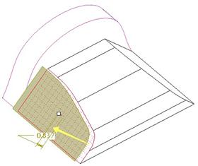
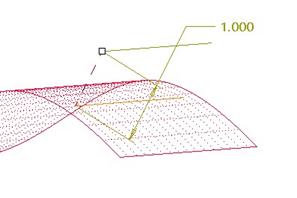
To create an offset curve, select the curve to offset (in this case the straight blue projected curve on the right side of the model), and then pick on the offset tool. When we do this, we will get the following preview on the screen.
If you grab the white square (drag handle) and move the curve over to the left along the surface, you will notice that the curve remains on the surface at all times. We will drop it on the left side of the originally selected curve, and change the offset distance to 1.0, as shown below.

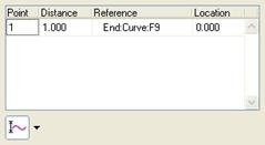
The dashboard for the offset curve looks like the following.
![]()
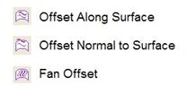
The first pull-down icon lets you select from three different offset types. The default is the “Offset Along Surface” option, which gives us the behavior that we have already seen. The three offset types are:
We will demonstrate each of these in upcoming sections. For now, we will click on the Measurements slide-up panel, which looks like the following.
Down in the lower left corner, there is another pull-down icon. The different options are:

Pictorially, the different options would give you the following result.
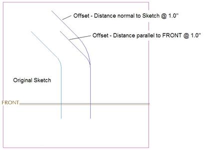
As we can see from the above figure, the option you choose will change the resulting curve drastically. We will leave it at the default of “Distance normal to curve/sketch”. Close the Measurements slide-up panel.
Offset Normal to Surface
In the dashboard, change the type to the “Offset normal to surface”. Rotate the model so you can see that the preview of the resulting curve now sits below the surface. Flip the arrow to place it above the surface at the same offset distance of 1.0, as demonstrated in the next figure.
NOTE: When creating an offset normal to surface, it is possible that not all segments of the selected curve/sketch will be created in the same offset feature. If this happens, you will need to split up your initial sketch into several and offset each segment individually.
Fan Offset
A “Fan Offset” occurs when you have two curves/sketches on the same surface, and you want to create curves between these – transitioning from one shape to the other at equally spaced intervals.
We will change our offset type to the “Fan Offset”. When we do this, our dashboard looks like the following.
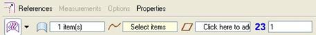
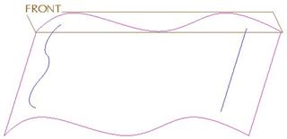
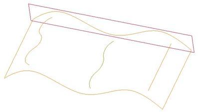
We have already selected our first curve/sketch to offset, now we are prompted to select the second curve/sketch. We will pick on the wavy curve on the left side of our surface, as shown in the next figure.

After we select this curve, we still need to define the offset direction. To do this, we must first click in the white field with the words “Click here to add…”, and then select a datum plane that is parallel to the offset direction.
We will turn on our datum planes and select the FRONT plane. When we do this, we will see the following preview.
Currently, the last field in the dashboard, labeled “23” represents the total number of curves to be created between our selected curves. The default value is 1, which is what we see on our model.
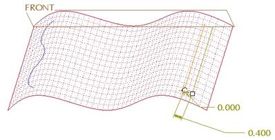
Change this value to 50, and then click on the green check mark once you see the preview to finish this offset curve feature.
Our resulting model will look like the following.
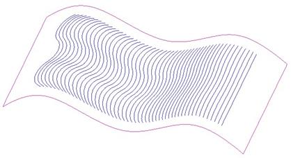
We can see that the curves start with the straight line and slowly develop into the wavy curve at the end.
Close this model when done.
LESSON SUMMARY
The Offset tool combines several different 2001 features into a single interface, controlled by what is initially selected (solid surface, quilt surface or curve).
EXERCISES
None