Lesson 130

Lesson Objective: In this lesson, we will learn about Rounds.

Rounds are used to remove sharp edges/corners in your model. They are generally very easy to create, but very easy to fail. For this reason, they should be modeled as some of the last features in your part, unless they are needed to complete another feature (other than another round).
Rounds that add material should be created separate from rounds that remove material, especially if they potentially intersect each other.
There are basically two types of rounds: Constant – the radius value is the same along the entire length being rounded, and Variable – the radius can change along the length being rounded.
Both of these rounds are created using the same round tool.
CREATING ROUNDS
To create rounds, click on the following icon in the feature toolbar.
![]()
Specify references to round. The thing to keep in mind is the concept of round sets. A round set is a single, tangent edge, or multiple, tangent edges that all have the same radius value. You can create as many round sets as you need (following the rule about adding/removing material).
To pick multiple edges to be in a single round set, use the Ctrl key on your keyboard, then pick the edges. To create a new round set, simply pick a new reference without holding down any keys on the keyboard.
You can still use the Shift key to get a chain of edges.
CONSTANT ROUNDS
SELECTING EDGES
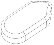
We will start by demonstrating how to create round sets with constant radii values. To do this, we will open up a part called Headset, which will initially look like the following.

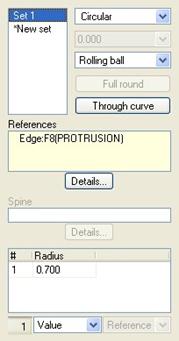
We will start creating rounds by picking on the round icon. In the dashboard, we will click on the Sets slide-up panel to see its contents. The dashboard looks like the following with the panel open.

We can see a column in the upper left. This column will keep track of the different round sets that we create. To the right of this column are several fields that define the shape of the round. The default, and most commonly used settings are shown above (Circular cross-section for the round, and Rolling Ball for the type of milling operation that would create such a round). There are other settings, but since they are not widely used, they will not be discussed in this guide.
In the References field, we will see a tally of entities that we select for the current active round set.
Below this is a field that lists the radius values used for the active round set. We will see this field in more detail when we talk about variable rounds. Right now, there are no references picked (hence the “No Items” text in the References field).
We will start by picking on the sharp edge at the top of the model. When we pick on it, it will highlight in a bold red, and a preview of the round with its current radius dimension will show up, as we can see in the figure below.
We can drag the white squares to dynamically update the radius value, or we can double-click on the radius dimension itself and enter a new value. We are going to change this radius to 0.7. The model will update, as shown below.

If we look back at the Sets panel, we can see the first round set listed, and we can see the references field includes the single edge that we picked. The radius value appears in the lower field, and in the icon bar at the very bottom of the dashboard.
Now, without holding down the Ctrl key, we will select one of the vertical edges at the other end of the rounded surface. Once we have one of them selected, we will hold down the Ctrl key to select the other. With both selected, modify the radius value to 1.2. Our model should look like the following figure.

The Sets panel now shows the second round set, the two edges used for this set, and the radius value applied.

It is currently the active round set because it shows up in red and yellow on the model. The first round set should be a muted cream color (when using the standard color scheme). In my illustrations, it appears as a dark gray outline of the dynamic preview for the round.
Now, we will create a third round set and pick the bottom two vertical edges. Remember to start the round set by picking on one of the edges without holding down any keys on the keyboard. Once you have the first edge selected, use the Ctrl key to select the other. Initially, they will take on the radius value of the previous round set, as we can see in the following figure.

What we actually want is to remove the surface at the bottom with a full round that goes all the way around, forming a semi-circle. We could enter a radius value that is equal to half of the width of the part, but if we later change the width, the round might fail, or at the least, no longer be a full round.
To preserve design intent, we will turn this round set into a full round. Looking at the Sets slide-up panel, we can see the third round set highlighted.

To the right of the sets list, we can see a button that is called Full Round. It will only be available if the current round set has two edges that are across from each other on the same surface.
Picking on this button gives us the following result on the model.

We can see that the radius value has disappeared. If we look at the sets panel, the radius value is dimmed here as well.

Now that we have all three round sets defined, we will click on the accept icon to complete this round feature. The model looks like the following.

If we were to look at the model tree, we would only see one round feature listed. This single round feature contains three separate round sets.
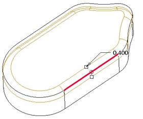
We will create one additional round for this model at this time, and that will be along the entire top edge of the model, with a radius value of 0.4. To create this, we will pick on the round icon, and then select one of the edges. It will automatically assume that any tangent edges to the one that we selected should also be rounded. This is a good assumption, because 99% of the rounds created are intended to round an entire tangent chain of edges.
The preview for this round looks like the following.
Accepting this gives us the following model at this time.
We will save this model and come back to it later.
SURFACE TO SURFACE ROUND
In addition to selecting edges to round, we may also select two surfaces that share a common edge. Look at the following model (Round2.prt).

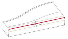
We are going to round the front, top edge by selecting two surfaces that share this edge. Therefore we will go into the round tool. Instead of picking on the edge (which is probably the easiest thing to do), we will pick on the left front surface, and then hold down the Ctrl key and pick the top flat surface. We will see a preview of the round, as shown below.
We will modify the radius to 0.5, and then accept this round feature. Our round will look exactly like an edge round, as we can see below.

ROUND THROUGH CURVE
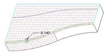
Another type of round is one that rounds an edge chain, but the radius is controlled by a datum curve or set of nearby tangent edges. We will continue with the same model as the previous section to demonstrate this.
We can see from the figures on the previous page, that we have a datum curve sketched on the top surface. We are going to use this datum curve to define the radius for an edge round on the back edge.
We will start by clicking on the round tool. We will pick the edge that we want to round first, as we can see in the following figure.
Then, we will expand the Sets slide-up panel to see the options, as shown below.

In this panel, we see a button entitled Through Curve. We want to pick on this. When we do, the panel will change slightly, as we can see below.

Instead of the field at the bottom with the radius values, we now have a field used to define the curve that we are going to follow. We will pick the datum curve on the model, and when we do, we will see the dynamic preview of the round.

We will accept this round, and our model will now look like the following.

THROUGH VERTEX/POINT ROUND
The last constant round we will demonstrate is one that uses a nearby vertex or datum point to define the radius value.
Look at the figure below to see the model that we are going to work with (Round3.prt).

We are going to round the front edge at the base of the rim that sticks up from the top of this part. But, we want the round to come up to the front edge. We could measure this distance and use that for the round, but if we change the model, that round will remain at a fixed radius.
Therefore, we want to use a vertex on the front edge as the radius value. That way, if we change the dimensions of the model, the round remains up to the front edge.
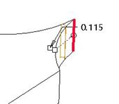
We will start by going into the round tool, and select the edge to round, as shown below, and use a value of 0.100.

We can see that the round goes up to the top of the rim, but stops short of the front. We will open up the Sets panel to make our change.

At the bottom of this panel, we see a field with the word Value in it. This field is used to determine how the radius is measured. Value means that we are going to enter a dimension value for the radius. This is the most common way to specify the radius, and that is why it is the default value.
If we pull-down this field, we see another option, called Reference. Reference allows us to specify the location by picking on existing geometry. The following figure shows what we are going to pick.
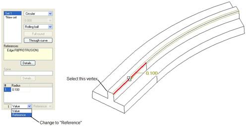
Once we select the vertex, our round should update, and the dimension value should disappear. We see a reference to the vertex instead.

In the lower right corner of the dashboard, we will click on the preview button (the eyeglasses) to see what this would look like if we accepted it right now.

VARIABLE ROUNDS
A variable round is one that changes in radius value as it traverses its edge. To demonstrate this, we are going to open the Var_Round model, which looks like the figure below.

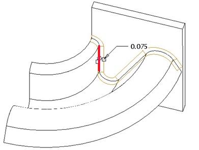
We want to round the top edge where the extruded and the revolved protrusions meet. We notice at the very right end of this edge, we come very close to the side of the plate. We could create a constant radius around this entire edge, but it will create a very ugly condition at the end, because it won’t be able to maintain its nice shape all the way to the endpoint.
Therefore, we are going to taper the round at this point. To do this, we will go into the round feature, and then select on one of the segments of this tangent chain of edges. Initially, the radius may come in very large. We want to modify it to 0.075, which will be our primary radius value for this edge. The round will initially look like the following.
You can see with the dynamic preview (shown above) that the round does not go all the way to the end as a constant radius. Therefore we need to make this a variable round. In order to make this a variable round, we need more than one radius. To add additional radii, hold the right mouse button down over one of the white squares (drag handles) where you see the existing radius dimension.
When we do this, we should get an option to Add Radius, as shown below.
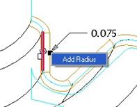
When we select this option, the existing radius dimension will snap to one end of the tangent edge chain, and a new radius will appear at the opposite end, as we can see in the figure at the top of the next page.

We could change the dimension value at the end now, but it would create a gradual taper across the entire length. We actually only want to start tapering as we come across the top of the rounded edge. Therefore, we will need another radius.
Holding the right mouse button over one of the drag handles on the leftmost dimension, we will select the Add Radius option again. It creates a new radius point, but places it on the same segment that the existing radius is on, as shown below.

We can see from the above figure that it has the same radius value as the original (0.075), but it also has another dimension (0.200). This is the length ratio for this radius. In other words, it represents how far along the current segment it lays in terms of a percent of the length. If we wanted this radius to be exactly at the midpoint of this arc, we would change this dimension to 0.5.
To move the radius to its proper location, we could place our mouse cursor over the white circle (which sits on the edge being rounded), and slowly drag it across the edge. You must keep your mouse cursor over the edge as you drag it, otherwise it doesn’t work.
For a very long edge, this could take some time. Instead, we are going to specify the exact location ourselves. To do this, open up the Sets panel. We can see the three radius points in the field at the bottom of this panel, as shown below.

For points 1 and 2 (which are at the endpoints of the tangent edge), we can see a Location called out as Vertex:Edge… For the third point (the new one that we just added), we can see a location of 0.200 (which was our length ratio). Below this field, we can see the word Ratio in a pull-down field.
To specify an exact location, we will use the pull-down to select Reference. When we do this, we can pick the exact vertex or datum point where we want to place the radius. We will pick on the vertex of the round going across the top, as shown in the following figure.

Now that we have specified all of the radius points, it is time to modify the values. The design intent for this round is to maintain the 0.075 radius until we get to the rounded edge, then taper down to a 0.0 radius value at the small end.
Therefore, we will modify the rightmost dimension to 0.0. Our dynamic preview will show us the result.

This is exactly what we want, so we will accept this round. The nice thing about the dynamic preview is that you can use it as a gauge to let you know if the feature will work or not. If the dynamic preview shows gaps across the edge, or is not visible at all, then the feature will not work. NOTE: Not all features in Pro/ENGINEER use a dynamic preview, however, so don’t get confused if you do not see one. You can always click on the full preview icon to test it before accepting it.
Our final model looks like the following.

ROUND TRANSITIONS
So far, we have only been talking about round sets. When you create a round feature, you start by defining all of the round sets. In many cases, that is all you have to do. There are some cases, however, where you will need to define transitions.
A transition is generally needed when two or more round sets converge at a non-tangent location, such as a sharp corner. The transition defines how the shape of the round will behave at such a location.
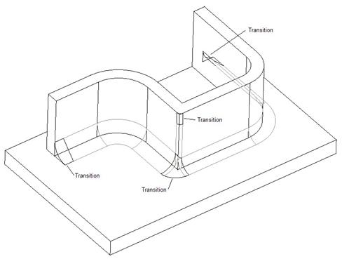
To demonstrate this, we will open up the following part (Round4.prt)

We want to round the three edges that converge into the sharp corner where the two protrusions meet. Each one of these rounds needs a different radius value per our design intent. The following figure shows what we want to do.

We know that we can create three separate round sets, each with a unique radius value, so that is how we will start.
We will go into the round tool, then select the three edges as separate round sets, and give each their respective radius value. It will not matter which order we go in, only that we have three separate round sets. The following figure shows these three sets after their radii values have been modified.

We can see that the dynamic preview for the three do not meet at the corner. They each have their own stopping point (at the ends of their segments). We will need to define a transition to ease these three rounds together. The Sets panel at this point looks like the following.

Down in the lower left corner of the dashboard, we see two icons, as follows.
![]()
The left icon is used to define Sets. It is selected as a default when you create a round. The icon on the right is used to define Transitions. We will click on that now.
In the model, any transition will highlight. You will have a possible transition at each of the following.
· Intersection of two or more rounds at a non-tangent location
· Any free end of a round set (where the end of the round is)
Our model has four potential transitions we could define, as shown below.
We only need to worry about the transition where the three round sets meet. If you move your mouse over the transition, it will pre-highlight. Select it so it becomes active. When active, it will turn yellow, as shown in the following figure.

In the dashboard, we will see a field that lists the current, default transition type.

The default transition type in this case is a Round Only 1. That is what you see in the preview on the model. If we use the pull-down arrow, we can see the other transition types that would work for this intersection.
They are shown in the following figure.

There are actually more transition types in Pro/ENGINEER, but you will only see the ones that will work at this time. If we move our mouse over the transition in this pull-down list, and watch our model at the same time, we will see it dynamically preview the transition in blue.
If I move the mouse over the Patch transition type, I would see the following preview on the model.

You can see that there are still some gaps in this transition type, so I would not put a lot of faith in the transition looking like it does above. If I place my mouse over the Round Only 2 transition type, I would see the following.

This looks as if it will bring my two larger rounds to a sort of chamfer, then round the top edge with the smallest round. I will go ahead and accept the default Round Only 1 transition type, then accept the round feature to complete it. Our final model looks like the following.

Just in case you are wondering what the result is for the other two transitions, here they are.

As I mentioned before, the Patch preview looked like it wasn’t working properly, so it defaulted to a Round Only 2 condition. That is why they both look the same.
LESSON SUMMARY
It is very easy to create rounds in Pro/ENGINEER, but you should try to create most of them as the last features, since they are primarily used to remove sharp corners.
The best reason for putting them last in the model is because they are often suppressed before exporting the model to an analysis package, such as ANSYS. If you must create them early, it should be because you need them for downstream features.
You should always avoid creating a non-round feature by tying it to an existing round. For example, you should not create an extrude feature and “Use Edge” on the round in the sketch. Of course, there are always exceptions in rare cases.
Create multiple rounds into a single set if they have the same radius value. Use Ctrl to do this. Create multiple round sets if you need different radius values. For multiple round sets that converge to non-tangent corners or edges, define transitions to smooth out the round.
EXERCISES
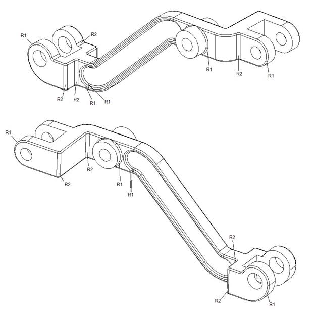
Open up the Hand_Rail_Column.prt part that we created in Lesson 12. Add the rounds shown in the figure on the next page.

Open up the Dash_Pot_Lifter and apply the rounds shown below. HINT: The order in which you create the rounds will have an effect on your ability to create them.