Lesson 120

Lesson Objective: In this lesson, we will learn about the Blend Feature.

BLEND DEFINITION
A Blend feature creates a single feature by blending sections of varying size, shape, and orientation.
There are three types of blend features.
· Parallel – All sections are parallel to each other separated by a blind depth for each section.
· Rotational – The sections are offset each other by an angle around a central axis of revolution, and a distance along the axis itself.
· General – The sections can be rotated in the X, Y, or Z direction as you create them.
To create a blend feature, we must use the menu commands Insert, Blend, then select one of the feature types shown in the following menu.

As with the sweep feature, the method for creating a blend is very similar from type to type.
PARALLEL BLEND
To demonstrate the parallel blend, we will create a part called Parallel_Blend. We will start by going to Insert, Blend, Protrusion. This brings up the following menu.

In the top portion of this menu, we are defining the type of blend we are going to create. We will keep Parallel as the option. In the middle portion of this menu, we are defining how the section will be handled. There are two options.
· Regular Sec – The section will be sketched on a plane or planar surface, and remain there when blended together with the other sections.
· Project Sec – The section will be sketched on a plane, but it will be projected onto a surface as part of the blend.
For now, we will keep the default option of Regular Sec as our choice. In the third section, we only have Sketch Sec available. For a Rotational or General blend, we would have the ability to select sections instead of sketching every one.
Once we have all of the options picked, we will click on Done. We will now be placed into the definition of the feature, and we see the following window.

We are currently defining the attributes, which are in the following menu.

There are two attributes to choose from: Straight or Smooth. If our blend feature only has two sections being blended together, then this will make no difference. If our blend feature has three or more sections, then a straight attribute connects them lienearly, almost like a connect the dot with straight lines.
A Smooth attribute connects them as a spline would going through points. You get a continuous, tangent edge from section to section. To start, we will keep Straight selected, and click on Done to continue.
We are now prompted to select or create a sketching plane. We will select the TOP datum plane. When we pick this plane, an arrow appears, as shown below.
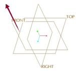
Unlike all of the other times when we were asked to accept the direction of viewing the sketching plane, we see the following prompt in the message window: “Arrow shows direction of feature creation. Pick FLIP or OKAY.”
We know we are still going to be looking at the TOP plane, but for a protrusion, the feature always comes towards us in sketch mode, while for a cut, the feature always goes away from us in the sketch. It will take a little getting used to, but eventually you will understand just how the sketch is going to orient based on what you pick.
Therefore, click on Okay to accept the direction as up, then face the FRONT datum plane towards the Bottom. We will now be placed in sketch mode.
We are going to sketch three rectangles to blend. We start by sketching the one that will eventually lie on the sketch plane, as shown below.

I am taking advantage of symmetry by using two centerlines. That way I only need to use two dimensions. I want to note where the start point is on this sketch. I will demonstrate why this is important a little later. For now, we just want to make sure that the start point is in the upper left corner for all three of our sketches.
Once I am done sketching this profile, I need to toggle to the next section using Sketch, Feature Tools, Toggle Section. The first rectangle becomes grayed out, and I can start sketching my second profile. The figure at the top of the next page shows this sketch with the second rectangle.

Note how the start point on this rectangle is equivalent to the location on the first one. Now we are ready to make our last rectangle. Once again, we will use Sketch, Feature Tools, Toggle Section. Now both our rectangles are grayed out for us to sketch the third, as shown below.

Once again, we are keeping the start point the same on all three. When we are finished with this rectangle, we will accept the sketch. In the message window, we are prompted for the depth of section 2. In other words, what is the blind depth between the sketching plane and the second rectangle that we sketched. We will enter 8.0. We are then prompted for the depth for section 3. This is the depth between section 2 and 3 (not the distance from the sketching plane to section 3). We will enter 5.0. We are then back at the window, where we can click on OK to finish this feature. The model looks like the following.

You can clearly see what the Straight attribute does, it makes sharp edges between sections. We will go to the model tree, right mouse click on this feature, and select Edit Definition to go back in and redefine this feature.
We are placed back at the window where we see the different elements we defined. The first one on the list is Attributes. If we double-click on this, we see the menu again where we originally picked Straight. Now, this time, we are going to select Smooth, followed by Done, then click on OK in the window to finish out the redefine. The model will regenerate, and look like the following.

This is quite a difference. Now, we have tangent edges going through the three sections. This makes for a more pleasing part. Now, we will edit the definition of this feature again. When we see the window pop up, we will double-click on section, followed by Sketch in the menu manager.
This will bring us back into the sketch, which now has the first rectangle active while the other two are grayed out. We will turn off the display of dimensions and constraints using the icons in the system toolbar for easier viewing of the sketch, as shown below.

We will toggle to the next section, and change the start point. To change the start point, click on a different vertex to highlight it, the right mouse click and select Start Point. We want to use the next corner in a clockwise direction, as shown below.

Toggle to the third section, and change its start point to the one shown in the figure below.

Once we have changed this last start point, accept the sketch, and then click on OK from the window to finish the redefine. The model will regenerate, and it should now look like the following.

There is a twisting effect going on here. The start point location is used to define how the entities are connected. Imagine that the sketch starts off by connecting all of the corners that have the start point, then it goes to the next clockwise corner for each section and connects those, and so on. This is how we got the twisting, because each section was connecting 90 degrees clockwise from the previous one.
ROTATIONAL BLEND
A rotational blend takes advantage of a sketched coordinate system. Instead of sketching all the profiles in a single sketch like we did with the parallel blend, we only sketch one, however, we must include a coordinate system in each sketch to tie the sections together. This will make more sense in the following demonstration.
We will begin by creating a new part called Rotational_Blend. Once inside, we will go to Insert, Blend, Protrusion from the menu bar. When the first menu comes up, we will pick on the following options: Rotational, Regular Sec, and Sketch Sec. This will bring up the following window.

We are currently defining the attributes. In addition to Straight and Smooth which we had in the parallel blend, we have two other choices: Open and Closed, as shown at the top of the next page.

We will see the difference between these two during this example. For now, we will keep the default of Open, select Smooth from the top choices, then click on Done to continue. We are prompted to select a sketching plane. We are going to pick FRONT. When we do, an arrow appears on the front plane, as we have seen it do many times before.

This time, however, the message window is asking for us to pick the direction of VIEWING the sketching plane again. The lesson you should have learned by now is to always look at the message window to see what you are being asked. It will save you a lot of time later.
We will accept this direction of viewing by clicking on Okay, then we will select the TOP plane to face towards the Top. Inside the sketch we will create our first section, which looks like the following.

The first sketch will be the only one that contains sketcher references. We want to create a sketched coordinate system and locate it at the intersection of the two sketcher references. The coordinate system shows the sketch as lying in the X-Y plane, where Y is going upwards. Once we have finished creating this sketch, we accept it.
In the message window, we are prompted to enter the rotation angle about Y. Using the right hand rule (thumb points in the direction of Y, and the direction your fingers curl represents the positive angle), we will enter a value of 30 degrees.
We are then placed into a new section. We are going to sketch the same profile as we did before. HINT: Use Sketch, Data from File, then click on the “In session” icon (little blue computer screen) to list all of the current sections that are in memory. The latest one on the list represents the one you are currently working on, so the one before that numerically is the last one that you did. Retrieve or sketch the following for the second section.

You will notice that there is a coordinate system in this sketch, because it is what ties this section’s location to the first one. Once we are done with this sketch, accept it. Down in the message window, we are asked if we want to continue on to another section. We will type Y for “Yes” and hit the enter key.
We will now be asked for the rotation angle for the next section about the Y axis. This will be the angle between section 2 and 3, so we will enter 60 degrees. We will be placed into the sketch, where we will create the figure at the top of the next page.

This sketch has different dimension values for the arc and the horizontal dimension at the top. If you choose to re-use a previous sketch, you will need to make these adjustments before moving on to the next section. Once you are done, accept this sketch, answer Y to create another section and then enter 60 for the angle.
Create the following sketch for the fourth section.

Accept this sketch and answer Y to create another section. Enter 30 degrees for this last angle, then sketch the following.

Once we are done with this last section, we will accept it, then answer N so that we don’t go on to another section. We will be placed back at the feature window. This time, make sure shading is turned on, and hit the Preview button in the window. Your model should look like the following.

Looking at the window, we can see there is an optional element we did not define. This is called Tangency, and it allows you to specify other surfaces that the open sections might be tangent to. In our model, we do not have any other features, so we really can not use this option at this time.
We will, however, change our attribute value. Double-Click on Attributes, and change the option from Open to Closed. Make sure you still have Smooth selected. Click on Done to accept this choice, then OK to finish the feature. You will now see the following model.

So, have you guessed how the Closed attribute works? It takes the first and last sections (as long as they are not touching), and attempts a revolve around the Y axis, blending the two together. It just happened that our first and last sections were identical, so it was able to create a semi-circular revolve to blend the two.
If you just looked at this model without knowing that it only took one feature to create this, you might think it was made up of complex surfaces, and datum curves, etc. This just goes to show you that you can get pretty complex shapes with very little feature headcount or complexity.
GENERAL BLEND
A General Blend combines the parallel and rotational blends, and adds the ability to rotate about more than one axis. Consider the following part (General_Blend.prt).

We can see the sections in the order in which we are going to pick them. These sections are already sketched datum curves. When creating general blends, it is often easier to create your sections as curves before you create the feature.
We will create the blend by going to Insert, Blend, Protrusion from the menu bar. At the first menu, we want to select the following options: General, Regular Sec, and Select Sec. We will hit Done to continue.
The window for the general blend opens up as follows.

This is the same window that we saw for the rotational blend, but the options we pick a little later will be different because we chose to select the sections. For the attributes, select Smooth, followed by Done.
The following menu comes up.

We are being asked to select the first curve. We want to select all four edges of each rectangle, so we are going to select on the Sel Loop option in the lower part of the menu, then pick on the first section curve, as shown below.

We can see that all four edges of this curve were selected, and we have a start point in the upper left corner. As we rotate our model around to select the other entities, we want to make sure we pick the same corner or we’ll get that twisting effect we saw earlier. Once we have the curves selected, pick on Done. We should see the same menu again (almost as if it didn’t take our previous selection). This is normal, because we have to specify at least two sections.
We are going to pick the Sel Loop menu command again, and this time we will select the second rectangle. When we pick it, it looks like the following.

All four edges were selected, but our start point is not in the right place. Therefore, click on the Start Point menu command, and pick the upper left corner. Once we do this, our sketch will update as follows.

Even though the arrow is pointing in a different direction, the fact that it is on the upper left corner is all that we care about. Pick on Done to finish this second section.
In the message window, we are asked if we want to continue on to the next section. Type in Y for yes. Repeat the process of picking using the Sel Loop command until all of the remaining three sections have been picked and the start points for all of them is in the correct orientation.
On the last section, we want to make sure that the point selected when looking from a top view is the lower left corner (because we want the part to rotate up 90 degrees at this point.
Once all of our sections are done, answer N to the last prompt about creating additional sections, then click on OK in the feature window to complete it. Our final feature looks like the following.

If the general blend fails, it is most likely that one of the start points was in the wrong location. Go back into the sections to fix any that were failing.
LESSON SUMMARY
Blends are a great tool to create complex transitions between different shapes. You can accomplish with a single blend feature what you might take dozens of surfaces, datum features and other entities to create, so don’t be afraid to try them.
You can either select sections or sketch them. Parallel blends will only let you sketch all of the sections in a single sketch using Toggle to go between them.
Always check the start points in the sections. Arranging them in different locations can cause twisting to occur, or feature failure.
EXERCISES
Create the part shown on the next page. Use a blend feature to create the main shaft of this part. Use Extrude and Revolve features for the remainder of the features.
Hand_Rail_Column
