Lesson 11

Lesson Objective: In this lesson, we will learn about the Sweep feature.

SWEEP DEFINITION
A sweep feature is created by taking a sketched profile and sweeping it along a sketched or selected trajectory. The cross-section of the feature along the entire length of the trajectory is constant.
In a later chapter, we will learn all about variable section sweeps, and how you can create a basic sweep in this feature. For now, we will concentrate only on the standard sweep feature.
CREATING THE SWEEP
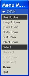
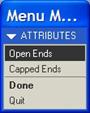
To create a sweep, you must use the menu bar, and go to Insert, Sweep. When you pick on the Sweep menu, you will get another menu showing all of the different options, as shown below.
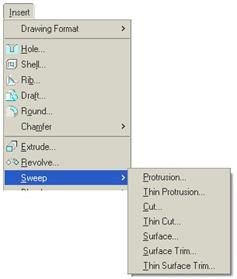
Unlike the extrude and revolve features that we have already seen, the Sweep feature makes you decide whether you are doing a Protrusion, Thin Protrusion, Cut, Thin Cut or Surface. Once you decide, you can not change it without deleting the feature and starting over.
The method for creating the five different types is identical, therefore we will demonstrate this with a solid Protrusion. Therefore, we would select the Protrusion menu option. Once we do this, we see the following window.

We saw a similar window earlier in lesson 8 when we created a datum curve through points. We can see in this window that we are currently defining the trajectory for our sweep. The menu manager appears just below this, and looks like the following.

We can either sketch a trajectory (if one does not yet exist), or select an existing set of edges or datum curves for a trajectory. We will choose the Sketch Traj option to sketch our trajectory. Once we pick this option, we get the next menu.

In this menu, we are asked to create or select a sketching plane. This is a different way to prompt us for this information than we have been used to, but we will see this type of prompt quite often with some of the more advanced (or less commonly used) features. In this menu, the option to select an existing plane is already selected (Plane). Therefore, we just need to pick the datum plane or planar surface that we want as our sketching plane.
We will pick the TOP datum plane. When we do this, an arrow appears on the model, as shown below.
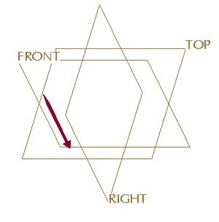
In the message window, we are asked to select the direction for VIEWING the sketching plane. The menu manager gives us two options, as shown at the top of the next page.

We can either flip the direction then click on Okay, or accept the current selection by clicking only on Okay. We will accept the downward direction for viewing. Once we do this, the menu changes once more.

Here, we are asked to select or create the sketching reference plane and its orientation. We will select the Bottom orientation, then pick on the FRONT datum plane on the model. Once we do this, we are placed into sketch mode.
We will create the following sketch.
We notice a yellow arrow on the sketch. This is the start point for our trajectory. This sketch is called an “Open Section”, since some of its endpoints are not touching each other. In an Open Section, the start point must be one of the open endpoints of the sketch (as it is above). If it is not, you must pick on one of the endpoints with the left mouse button so it highlights, and then right mouse click and select Start Point.
The Start Point represents the location where your profile starts from. We want it to be on the straight segment for this example. Once our sketch is complete, we accept it by clicking on the blue check mark. We are then placed into the sketch for the profile that we are sweeping.
We will create the following sketch for this profile.
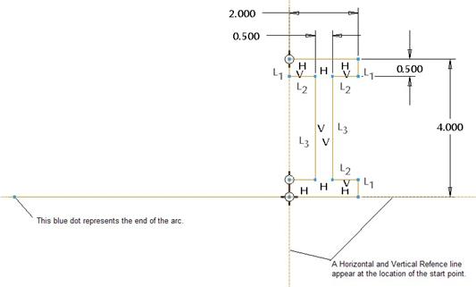
When you sketch the sweep section (profile), there will always be a horizontal and vertical reference line that forms a “Crosshairs”. This “Crosshairs” marks the location of the start point. If you are not sure how you are looking at the trajectory, I strongly recommend rotating your model slightly to see. You can always pick View, Orientation, Sketch Orientation to return to the sketch view.
IMPORTANT! – When you have an open trajectory, you must have a closed section for your profile for a solid protrusion. We will see how to handle a closed trajectory in a few minutes.
Once you are done sketching the profile, accept this sketch. All of the elements are now defined for this trajectory. We can click on OK from the window to complete the feature. Our model now looks like the figure at the top of the next page.
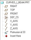
The symbol for a sweep can be seen by looking at our model tree, as shown below.
CLOSED TRAJECTORIES
In this example, we will show the slight difference in creating a sweep that has a closed trajectory. We will start the same way that we did before by going to Insert, Sweep, Protrusion from the menu bar at the top.
We will continue the same way by sketching a trajectory, and then using the TOP datum plane as our sketching plane, and FRONT datum plane facing towards the Bottom.
Our sketch for our trajectory will look like the figure on the next page.
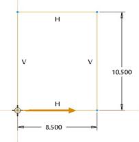
This is a simple closed rectangle. Once we are done sketching our trajectory and accept our sketch, we get a different menu option.

Our two choices are:
· Add In Fcs – Add Inner Faces – This requires you to sketch an open profile, and as it sweeps around, it connects across all of the open endpoints to form an inner face. This is great for closed picture frames, or other parts where the outside is definitely a swept profile, but the middle is closed.
· No Inn Fcs – No Inner Faces – This requires you to sketch a closed profile. There will be no inner face that results from this. This would be ideal for an open picture frame (with no back plate).
In this example, we will select Add Inn Fcs, and then click on Done to continue. We are now placed into our section for our profile. We will sketch an “OPEN” section, as shown below.
We can see the two endpoints of this sketch. As the profile is swept around the rectangle, the top endpoint will connect to itself at all locations across the center of the part, while the bottom endpoint does the same. Everything in between becomes a solid mass.
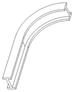
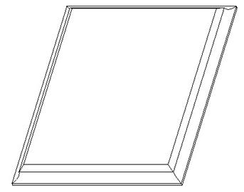
When we accept this sketch and click on OK to complete the feature, we can see the following model.
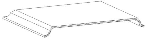
If we made a cross section through the middle, we would clearly see the solid mass that was created, as shown below.
SWEEPING SURFACES
Sweeping surfaces is no different than sweeping protrusions, cuts, etc. The biggest difference is that you don’t need to have a closed section. If you have an open trajectory or closed trajectory, you can still have an open profile.
The biggest difference is that if the trajectory you are using is the edge of another surface, you may be asked to Join or No Join. If you select Join, then you are performing a Surface Merge at the same time. If you select No Join, then the new swept surface will be separate from the surface whose edge acted as the trajectory, and a merge operation will still need to be performed to get them to be one large quilt.
SELECT TRAJECTORY
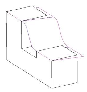
We will finish this lesson off with a demonstration of the select trajectory by picking on an existing curve to create a swept surface. Let us look again at the following part that we saw earlier.
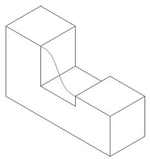
If you recall, we have a copied curve that makes up the top left edge, the datum curve in the middle, and the top right edge. We will use this curve as our trajectory for our surface sweep.
NOTE: Sometimes copied curves do not work for regular sweeps if they lie in three directions. The curve that we are using here is still a two-dimensional curve, because it is co-planar with the front surface of our part.
We will start the sweep the same way, picking Insert, Sweep, Surface from the menu bar. When prompted, pick on Select Traj to select the trajectory. You will then see the following menu.
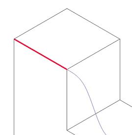
Since we are picking a datum curve, we will use the Curve Chain option, then pick on the top left edge, as shown below.
When you pick on a single segment of a curve chain, we get a little menu that pops up that looks like the following.

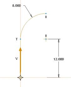
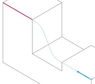
If you want the entire curve used as the trajectory, pick on Select All. If you only want a certain portion, then select From-To and pick the starting and ending endpoints of the curve. We want the entire curve, therefore we will pick Select All. The entire curve highlights in blue, and our start point is shown with the blue arrow, as we can see below.
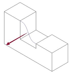
Now that we have what we want for a trajectory, we click on Done to stop selecting and accept what we have. Another arrow appears on the model, as shown below.
If you recall when we sketch the profile, there is a horizontal and vertical reference line on the sketch at the location of the start point. When you select a trajectory, Pro/ENGINEER wants to know which way to orient the sketch. It highlights an adjacent surface or part of the trajectory selected, and in the message window it says.
“Select upward direction of the horizontal plane for sweep section.” If we click on Okay in the menu manager, then the front surface of our part will be facing up in the sketch. You will want to pay close attention to which surface it is pointing, because it may make it easier or harder to sketch your profile.
We will click on Okay to accept the default direction. Had there been more than one possible surface to pick, it would have prompted us to first pick the surface that we are going to face upwards before picking the direction.
With a surface feature, we are given the option to create end surfaces or leave them open. The menu that comes up gives us these options, as shown below.
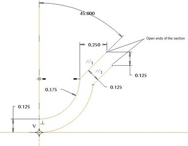
We will leave the ends open, so click on Done to continue. We are then placed into sketch mode to sketch our profile. We will sketch an open profile (which if you remember was not allowed for a solid protrusion). The figure at the top of the next page shows our profile.
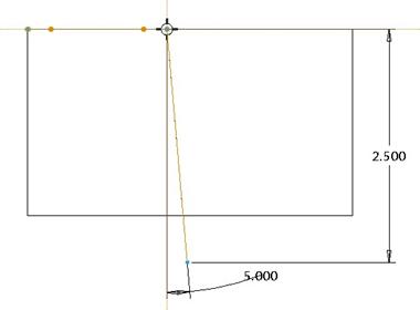
We just sketched a straight line at an angle to the vertical reference. Once we are done, we accept the sketch then click on OK to complete the feature. Our model looks like the following.
LESSON SUMMARY
The sweep tool is used to pass a profile along a trajectory that you either sketch or select.
Depending on the section for the trajectory (open or closed), you will have restrictions on what type of section you can have in the profile.
For a closed trajectory, you can add inner faces or leave the part hollow. For surfaces, you can also create end surfaces as well.
EXERCISES
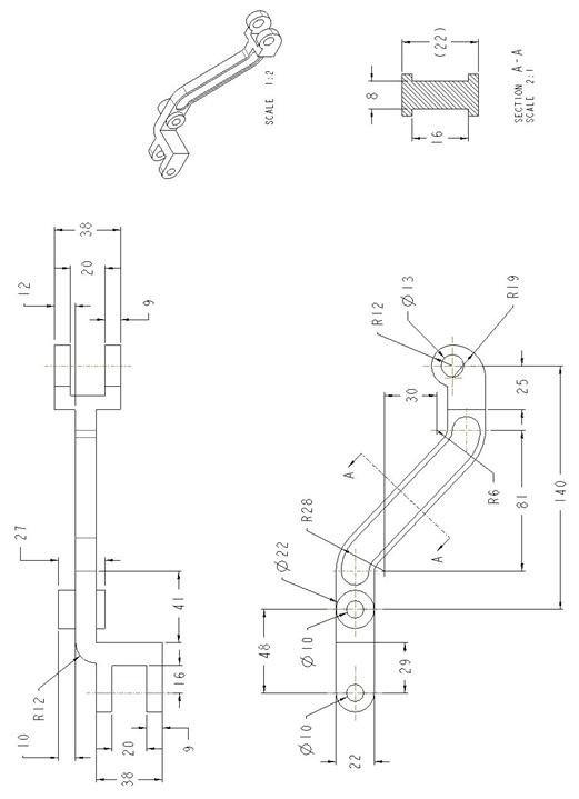
Create the parts shown on the following pages. Use a combination of extrude, revolve and sweep features where applicable, and create any datum geometry necessary to complete your model.
Dash_Pot_Lifter
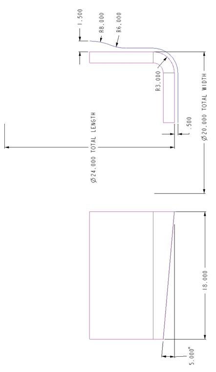
Basket_Prt (Continued)
Open up the Basket part that we started in lesson 8. Create a swept surface using the inside trajectory. For the profile, sketch a line angled inwards from the trajectory by 5 degrees to a depth of 18 inches, as shown below.