Lesson 4

Lesson Objective: In this lesson, we will learn about the sketcher functionality.
STAND-ALONE SKETCHER
Many of the features in Pro/ENGINEER require you to sketch a profile then perform some sort of operation on that sketch, such as extrude, revolve, sweep, etc. When you are creating features that require a sketch, you enter sketch mode through the feature.
To introduce sketcher functionality, we are going to create stand-alone sketches. The only time you ever create stand-alone sketches (besides for training purposes), is to create sketches that you can re-use. We will see examples of importing saved sketches into feature creation later in this guide.
For now, please understand that you normally will not enter sketch mode as a stand-alone process.
To start a sketch in stand-alone mode, go to File, New from the menu bar, or click on the following icon in the system toolbar.
![]()
When the window pops up, select the Sketch type, which has no sub-types. In this example, I am going to call this sketch Latch_Plate. The window will look like the following.

Clicking on OK brings you into the sketch. The figure at the top of the next page shows the sketcher toolbar, which appears at the right side of the working window, in the feature toolbar.

SKETCHER STEPS
To effectively use sketcher, it is highly recommended that you follow these steps in this order.
1. Select/Deselect References – If entering sketch mode in the middle of creating a feature, and there is already geometry in your model, then this step applies. Otherwise, for stand-alone mode, skip this step.
2. Sketch Quickly – Your goal when sketching is to capture the basic shape, but not to worry about looking perfect, or even getting close to the proper size. If you spend too much time sketching, then you are using it incorrectly.
3. Add Constraints – Add any constraints to the sketch to reduce the number of necessary dimensions (such as equal length, or perpendicular, etc.)
4. Dimension Completely – As you will see, sketcher does not allow you to under- or over-dimension a sketch, but you should use basic manufacturing principles when adding dimensions. Remember design intent when doing this, because the dimensions that you add in the sketch are the ones that you are going to use to make changes later, so pick dimensioning references wisely.
5. Modify Dimensions – Only after all of your entities are sketched, constrained and fully dimensioned, should you modify the dimensions to their proper values. Modifying the dimensions as you go may cause the sketch to warp or fail regeneration. There are tools in the modify command to stop regeneration or to scale the sketch. We will see this in more detail coming up.
6. Finish – Once your sketch looks good, accept the sketch to continue the feature creation, or to finish out of the stand-alone sketch.
LINE TOOLS
If you click on the Line Tools Icon, it will expand to reveal the following line types.

LINE
Using the left mouse button, click where the start of the line is, then move your mouse to the location where the end of the line is. Click again with the left mouse button to place the end of the line.
The line tool remains active, allowing you to pick the endpoint of the next line (which starts at the end of the first line). Continue selecting locations for line endpoints until you have sketched all lines, then use the middle mouse button to complete the line tool.
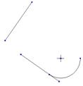
The following figure shows sample lines. NOTE: The display of dimensions and constraints have been turned off in the figure below. Each sketch segment contains a blue dot locating its endpoint.

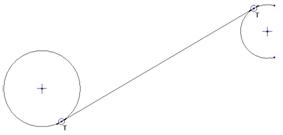
TWO-TANGENT LINE
This line entity is created tangent to two circles, arcs or combination of the two. With the left mouse button click on one arc/circle, then move your mouse over to the other arc/circle. The line should automatically adjust itself to snap tangent to both entities (at both ends). Click with the left mouse button once you see the tangent snap occur.
This line tool remains selected, but not active (in other words, you must start a new one by picking on the first arc/circle again, instead of continuing at the endpoint of the previous line).
The following figure shows a sample two-tangent line between an arc and a circle. NOTE: The display of constraints has been turned on, but the display of dimensions still remains off. Notice the small “T” symbol that appears at each endpoint. This shows the tangent condition.
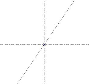
CENTERLINE
Centerlines are used as snap lines, symmetry lines (for mirroring) or as axes of revolution if creating a revolved feature. When you sketch a centerline, its length occupies the entire working window.
You click once with the left mouse button to locate a point on the line, then move your mouse until it is in the orientation that you want. Click with the left mouse button again to finalize the line.
The centerline tool remains selected, but not active in the working window. The following figure shows three centerlines. At their intersection, a sketch point appears automatically.
RECTANGLE TOOL
The rectangle tool is only a single icon, shown below.
![]()
To use the rectangle tool, use the left mouse button to locate one corner of the rectangle. Move your mouse to the location of the opposite corner, and then click with the left mouse button again to finish the rectangle.
The following figure shows a sample sketched rectangle. Again, the display of dimensions and constraints has been turned off.

CIRCLE TOOLS
If you click on the Circle Tools icon, it will expand to reveal the following tools.

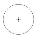
CIRCLE
To use the circle tool, click with the left mouse button to locate the center of the circle, then move your mouse to adjust the diameter. Click again with the left mouse button to place the diameter.
The following figure shows a sample circle.
CONCENTRIC CIRCLE
The concentric circle tool creates a circle whose center lies at the center of an already existing circle or arc. To create this, use the left mouse button to select an existing circle or arc on the sketch. Then, move the mouse cursor to drag out the diameter. Click with the left mouse button again to place the diameter.
This circle tool remains active, and allows you to create multiple circles with different diameters located at the same center point. To cancel out of this circle, click on the middle mouse button.
The following figure shows a concentric circle at the center of an existing arc.

THREE-POINT CIRCLE
The three point circle is created by clicking or selecting any three sketch points, vertices or general locations on the sketch. When you click on the second point, the circle will appear, and the third point locates the diameter.
The following figure shows a sample three-point circle using three random locations on the sketch.

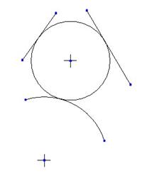
THREE-TANGENT CIRCLE
The three-tangent circle is created tangent to three entities (lines, arcs, etc.) To create this, use the left mouse button to select the three entities the circle is to be tangent to, and the circle is created automatically.
The following figure shows a sample three-tangent circle using two lines and an arc.
ELLIPSE
An ellipse is a circle that is longer in one direction and shorter in another (like an egg). The ellipse tool in sketcher creates only horizontal or vertical ellipses, however you can use the transform tools to rotate it 45 degrees, for example.
To create the ellipse, use the left mouse button to locate the center of the ellipse, then move the mouse to locate the horizontal and vertical radii. If you move more to the left or right away from the first point than you do up or down, you create a horizontal ellipse, and the opposite creates a vertical ellipse.
The figure at the top of the next page shows a sample horizontal ellipse.

ARC TOOLS
Clicking on the arc tools icon expands it to reveal the following tools.

TANGENT-END / THREE-POINT
This general arc tool gives you two different options. The Tangent-End arc tool creates an arc that is tangent to an existing line or arc at its endpoint. To create this arc, use the left mouse button to select the open end of an existing line or arc segment. When you do this, a special symbol appears at the end, which looks like a green circle with a big “X” through it, as shown below.

The “X” breaks up the circle into quadrants. Depending on which quadrant you move your mouse out from, you will either get a tangent arc or a three-point arc. The following figure shows the quadrants that affect the result.

To create the tangent arc, bring your mouse out of the circle in the quadrant at the end of the line segment (indicated above), and then use the left mouse button to locate the free end of the arc.
The following figure shows the resulting tangent-end arc. Note the “T” symbol at the intersection of the arc and line segments. This is the tangent constraint.

The Three-Point arc is created by picking on the two endpoints of the arc, then dragging out the radius. When starting from an existing line or arc segment, be sure to come out of the quadrants to the side of the existing segment to avoid a tangent-end arc. The following figure shows two three-point arcs (one from an existing segment, and the other just by itself.

CONCENTRIC
A concentric arc is created by using the left mouse button to select on an existing arc or circle, then move the mouse cursor to drag out the radius. While the radius shows up in a dashed circle, use the left mouse button to select the start of the arc, then move your mouse to locate the end of the arc. Click with the left mouse button to place the end of the arc.
As with the concentric circle tool, the concentric arc tool remains active, allowing you to create multiple concentric arcs on the same center. To finish out of this tool, use the middle mouse button once you have completed your desired arc(s).
The following figure shows a concentric arc using an existing circle to determine the arc center.

CENTER-ENDS
The center-ends arc is created by using the left mouse button to select the center of the arc. Move your mouse cursor to drag out the radius of the arc (which is indicated by a dashed circle), as shown in the following figure.

Use the left mouse button to select the start point of the arc, then move your mouse to locate the end point. Once you have located your end point, click with the left mouse button to place this end point. The figure below shows the resulting center-end arc.

THREE-TANGENT
Similar to a three-tangent circle, a three-tangent arc is created by using the left mouse button to select three entities the arc will be tangent to. The first two points determine the endpoints of the arc, while the third point selected is used to determine the radius. The following figure shows a three-tangent arc using two line segments and an arc.

The “T” constraint symbols appear at the location where the tangency condition exists.
CONIC
A conic arc is an arc that does not have a circular profile to it (similar to an ellipse). You create the conic arc by using the left mouse button to pick the two endpoints of the arc, then drag out the radius. A centerline is created automatically through the endpoints. The following figure shows a sample conic arc.
FILLET TOOLS
Expanding the fillet tools icon reveals the following tools.
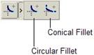
CIRCULAR
A circular fillet creates an arc tangent to two entities (lines, circles, other arcs, etc.) that has a circular profile. The result is the removal of the corner (or projected corner if the two entities are currently not intersecting) and the creation of the arc.
To create, use the left mouse button to select the two entities at the location where you want the fillet. The fillet will be created automatically using a best-fit method. The figure below shows a sample circular fillet.

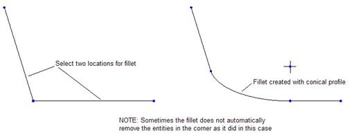
CONICAL
The conical fillet is created the same way you create a circular fillet. The only difference is that the resulting fillet does not assume a circular profile, and therefore does not have to do a best fit.
The following figure shows a sample conical fillet.
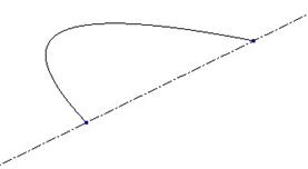
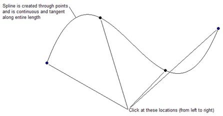
SPLINE TOOL
The spline tool is used to create a continuous, tangent entity that passes through specified points. To create a spline, pick on the following icon.
![]()
Then, use the left mouse button to select points in a row. As the points are selected, the spline will update to remain tangent and continuous (no sharp corners). Once you are done selecting points, use the middle mouse button to complete the spline.
The following figure shows a sample spline.
SPECIAL ENTITY TOOLS
Clicking on the icon will reveal two special sketcher tools, as shown below.

POINT
A sketcher point is used in various ways. One simple way it is used is to create a snap point to tie multiple entities together. For example, you might use a point to force an arc to lie on a line segment.
Sketcher points are also used to create Datum points if you use the “Sketched Datum Point” feature.
Another use for sketcher points would be to create blend vertices. This is, for example, when you blend a square into a triangle, you have four endpoints in one entity but only three in the other. The blend vertex forces two entities in the square to connect up to a single vertex in the triangle.
The following figure shows a point used to tie two entities together, and a point all by itself.

COORDINATE SYSTEM
A sketched coordinate system is used for some specialized features, such as torroidal bends, helical sweeps, general blends, etc. To sketch a coordinate system, pick the location where you want the coordinate system. The coordinate system always has the X-Y arrows in the sketch, and Z points outwards. The following figure shows a sketched coordinate system.

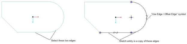
USE EDGE / OFFSET EDGE TOOLS
When we are sketching a new feature in a model that already has geometry, we have the ability to use existing edges in the model as a basis for the sketch entities. Clicking on the Use Edge / Offset Edge icon shows us the two tools.

USE EDGE
To create a sketched entity by exactly placing it on top of existing edges in the model, use this tool. Click with the left mouse button on the model edges you wish to use. The complete edge will be copied into the sketch, and a backwards “S” symbol appears on the edge, indicating that it is a use edge.
The following figure illustrates this. NOTE: The existing model edges are blue in this figure, and the sketched entities are black.
OFFSET EDGE
To create a sketched entity by offsetting existing edges in the model, use this tool. When you click on the Offset Edge icon, you get the following menu choices (which you also got for the Use Edge command as well).

If you use Single you will pick on an edge, then specify the offset distance for that single edge. To get all of the edges around a surface, select Loop, then specify the overall offset distance for all edges.
To select a chain of edges, pick on Chain, then pick the first edge in the chain, followed by the last edge in the chain, as shown in the figure at the top of the next page.

A new menu will appear giving you the choice to accept the highlight as it currently shows, or to toggle through other possible edge chains based on the two segments you selected. The menu looks like the following.

Once you accept the chain, a red arrow will appear on the sketch, and the message window will prompt you to enter an offset value. The direction of the arrow indicates a positive offset. The following figure shows this arrow.
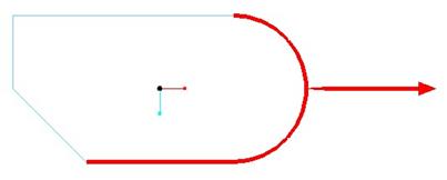
If we were to enter a positive value for the offset distance, then our sketch entities would appear outside of the existing model. If we enter a negative value, then our entities offset towards the inside of the model. The following figure shows a negative offset value entered. Again, note the backwards “S” symbol indicating that these edges are offset.

DIMENSION TOOL
As you sketch, dimensions should appear on the model automatically. These dimensions initially appear gray and muted. This is known as a weak dimension. Weak dimensions are added to ensure that the sketch is always fully defined (no over- or under-dimensioning).
The following figure shows an example of weak dimensions applied to a sketch before any dimensions were manually applied.

Let’s take a minute to break down what we see above. We can see the existing model geometry (in blue), and the sketched entities (the lines that form a sort of “L” shape).
We can see some constraints that are already on the sketch (the “H” and “V” symbols).
In addition, we can see two dashed lines. These lines are sketch references. We will talk about these later in this lesson.
There are two sets of dimensions that you will have when you sketch to create a feature in an existing model. These are:
· Locating Dimensions – Dimensions that locate the sketch with respect to existing geometry. Often, these dimensions go between the sketch references and the sketched geometry.
· Shape/Size Dimensions – Dimensions that control the shape and size of the sketch that we made.
You may not always have locating dimensions if you constrain the sketch to existing references or geometry (such as using a Use Edge or Offset Edge tool).
Initially, all of these dimensions are weak. You want to make sure that you never leave weak dimensions in your sketch, because they are not stable, and could disappear. We will demonstrate this as we start to add dimensions.
NORMAL DIMENSIONS
To create normal dimensions, click on the following icon in the sketcher toolbar.
![]()
Click on the entities to dimension using the left mouse button, then place the dimension using the middle mouse button. Now, we will demonstrate the different types of dimensioning schemes.
Linear Dimensions
Linear dimensions measure the distance between two entities in a single distance, or the length of a line segment. The following figures illustrate linear dimensions.
results in…

The strong dimension shows up in a creamy yellow on the sketch (shown in black in this training guide). Notice how one of our weak dimensions disappeared? The weak 2.046 dimension in the first figure went away once we added our strong dimension, because it maintained a fully-defined sketch. We could have just as easily lost the 4.092 dimension instead of the one we did lose.
The fact that weak dimensions can arbitrarily disappear when we add strong dimensions is the primary reason we want to make sure all the dimensions are strong.
We don’t have to redo create a dimension if we already have a weak dimension where we need one. To make the weak dimension strong, we can either modify the dimension, or force it to be strong.
To force a weak dimension to be strong, first select the dimension so it highlights in red, then click with the right mouse button to see a list of options. Select the Strong option to make this dimension strong, as shown below.

Once we do this, the dimension should turn creamy yellow (black in our case), as we can see in the following figure.

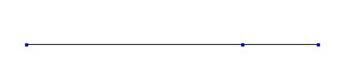
To create a dimension for the length of a line, click once on that line with the left mouse button, the place the dimension using the middle mouse button. The following figure illustrates this.

You can also create linear dimensions by picking on two arc/circle centers or two vertices. The following figure illustrates a linear dimension between two vertices.

Angular Dimensions
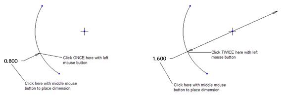
To create an angle dimension between two entities, click on the two entities with the left mouse button, the place the dimension in the correct location with the right mouse button. The location determines what type of angle you are going to get.
Consider the sketch below.
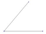
There are four possible places to specify and angle on this sketch. The following figure shows the different scenarios for specifying the location to get the different angles.

In the figure above, you select both line segments with the left mouse button, and if you click with the middle mouse button in the shaded area, you get the resulting angle dimension shown to the right of that figure.
Radius/Diameter Dimensions
To create a radius dimension on an arc or circle, click once on the arc or circle with the left mouse button, and then place the dimension with the middle mouse button.
To create a diameter dimension on an arc or circle, click twice on the arc or circle with the left mouse button, and then place the dimension with the middle mouse button.
The following figure illustrates this.
REFERENCE DIMENSIONS
If you need to call out more dimensions than are necessary for the sketch to be fully defined, you should use reference dimensions.
Reference dimensions, unlike normal dimensions, can not be modified directly. They are what are called driven dimensions. Changing normal dimensions will cause the reference dimension to update.
A reference dimension is created exactly the same as normal dimensions (from a standpoint of picking with the left mouse button and placing with the middle mouse button), but to access reference dimensions, go to Sketch, Dimension, Reference from the menu bar at the top.
Then, pick your references. The following figure shows a reference dimension.

Notice how reference dimensions have parenthesis “( )” around them?
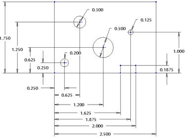
ORDINATE DIMENSIONS
Typically, you use ordinate dimensioning to reduce the screen clutter on a drawing. These are very useful for objects with hole patterns, or many, complex shapes.
To start an ordinate dimension, we need to create Baseline dimensions. A Baseline dimension marks the “Zero” location from which all ordinate dimensions are measured from. There are typically two baseline dimensions in an “X-Y” coordinate system, one that determines the horizontal zero and the other that determines the vertical zero.
The following figures show the difference between linear and ordinate dimensioning (maintaining the same design intent).
Linear Dimensioning Scheme
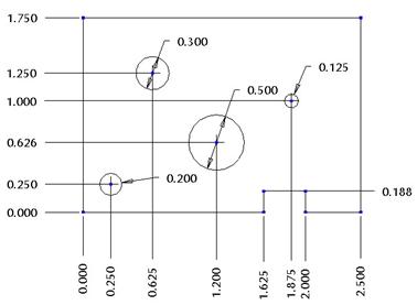
Ordinate Dimensioning Scheme
Notice how much cleaner the ordinate dimensioning looks? You can also create a combination of the two. The following figure shows this for the same sketch, preserving design intent.

Would you want to do this? You’ll notice that in the figure above, ordinate dimensioning is used for the hole locations, but the rest of the model uses linear dimensions. Perhaps on your drawing, you may have a separate view detailing the hole pattern, and may wish to use ordinate dimensions for that view, but for the other view that calls out the overall dimensions of the part, you may wish to maintain the linear dimensioning scheme.
My recommendation is to reduce the number of views in the drawing that it takes to CLEARLY call out your design intent, and using ordinate dimensioning across the board may accomplish this where linear dimensions may be too messy.
To create ordinate dimensions, go to Sketch, Dimension, Baseline, and then click on the entity with the left mouse button that represents one of the “Zero” locations. Place the “0.000” dimension along the entities’ direction, as shown in the figure below.

The baseline dimensioning tool remains active, so you can simply pick the next line and place the dimension, as shown below.

Once you have your baseline dimensions created, you can create the ordinate dimensions. To do this, click on the dimension icon in the sketcher toolbar (just like we do to create normal dimensions), then click in this order.
1. Pick on the baseline dimension, with the left mouse button, that runs in the same direction as the ordinate dimension you wish to create.
2. Pick on the entity to dimension with the left mouse button.
3. Use the middle mouse button to place the dimension.
The following figure illustrates this.

Repeat this process to create the other ordinate dimension; (pick the other baseline to start, followed by the top edge, and then place the dimension).

MODIFY TOOL
The easiest way to modify a dimension in the sketch is to double-click on that dimension with the left mouse button and type in a new value. Once you hit the Enter key (after modifying the value), your sketch should automatically regenerate to reflect this change.
The following figure shows what the screen would look like once you double-click on the dimension.

Once you modify a dimension, it becomes strong (if it was previously weak).
MODIFY TOOL ICON
If you have a complex sketch, sometimes modifying dimensions using the double-click method causes the sketch to distort. Sometimes, you can not modify a dimension value if the starting value and ending value are so drastically different that the sketch can not successfully regenerate.
In these cases, you will want to use the modify tool by picking on the following icon in the sketcher toolbar.
![]()
Before using this tool, you have two choices. You can either select the icon, then select on the dimensions to modify, or use the select tool and the Ctrl key on your keyboard to select all of the dimensions ahead of time and then click on the icon.
We will do the latter for this example. We will modify all of the dimensions in the figure below.

To do this, use the select tool ( ![]() ), and then drag a box around the entire
sketch. When you release the left mouse button, all entities and dimensions
will highlight in red. At this time, click on the modify tool icon.
), and then drag a box around the entire
sketch. When you release the left mouse button, all entities and dimensions
will highlight in red. At this time, click on the modify tool icon.
A window will appear. I have moved this window next to the sketch so you can see both simultaneously, as shown below.

You will notice that all dimensions that are highlighted are listed in this window. One of them is currently selected (indicated by the blue shading in the field). On the sketch itself, the selected dimension will have a box around it (currently the total height dimension).
The components of this window are shown in the following figure.

You can change the dimensions by typing a new value in the field provided, or by moving the sliders to the right of the dimension to dynamically update them. We want to pay close attention to the two options in the lower left, which are:
· Regenerate – By default this is selected (green check mark). Turn this off to prevent the sketch from automatically regenerating as you modify the dimension values. This will let you modify all of the dimensions and then regenerate the sketch all at once.
· Lock Scale – To use, turn this on BEFORE modifying any dimension values. Once activated, the first dimension you modify will drive all other dimensions to update so the sketch maintains its current aspect ratio.
For example, suppose you have a rectangle that is 2 inches long and 1 inch wide. The length to width ratio is 2:1. If we really want the length to be 200 inches long, to maintain the same aspect ratio, the width would have to be 100.
If we were to click on Lock Scale, then modify the length dimension to 200, the width would automatically update to 100. This is very useful if you need to make a drastic dimension change and you don’t want your entire sketch to distort or warp on you.
CONSTRAIN TOOL
As we sketch in Pro/ENGINEER, we will notice some constraints that appear automatically. Pro/ENGINEER’s sketcher tool is smart enough to make some assumptions (which may not be what you ultimately want sometimes).
For example, if you sketch a line approximately in the horizontal direction, sketcher will assume you want a horizontal line and snap it to that automatically. An “H” symbol will appear on the line when this occurs. If you don’t want a horizontal line, then exaggerate your line so it is more of a 30 degree angle (for example) with the horizontal.
You can disable an automatic constraint by simply selecting on it after you sketch so it highlights, and press the Delete key on your keyboard. For example, if you sketched a horizontal line, and really wanted it to be angled, you would click on the “H” symbol so it highlights in red, then delete it.
To add additional constraints to your sketch that might not have been “assumed” click on the following icon.
![]()
This will bring up the following window.

The different tools are:
· Vertical Line / Line up Vertically – Make any line segment a vertical line or take two vertices and line them up on an invisible vertical line.
· Horizontal Line / Line up Horizontally – Make any line segment a horizontal line, or take two vertices and line them up on an invisible horizontal line.
· Perpendicular – Take two entities and make them perpendicular to each other.
· Tangent – Take two entities and make them tangent to each other (usually an arc to a line, an arc to an arc, or a circle to a line or arc).
· Midpoint – Force a point, coordinate system or entity endpoint and make it at the midpoint of another entity.
· Collinear / Aligned – Make two line segments line up with each other, or place the endpoint of an entity and snap it to another entity (anywhere on that entity).
· Symmetric – Make two vertices lie equidistant from a sketched centerline to create a “mirror” effect.
· Equal Length / Radii – Make two line segments equal in length, or make two circles or arcs or combination of both equal in radii.
· Parallel – Make two line segments parallel to each other.
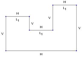
To demonstrate this, look at the following initial sketch.

The display of dimensions has been turned off so we can more clearly see the constraints that are on the entities. As we can see, there are a few horizontal and vertical constraints added automatically as we sketched this profile.
Now, suppose we want the bottom line to be horizontal, the three top horizontal lines to be equal in length, and finally the top left and top right horizontal lines to line up with each other.
First, we’ll address the equal length lines. Start by clicking on the constraint icon that represents Equal Length / Radii. Then, select the two lines shown in the following figure.

The lines should snap to be the same length, and an L# symbol appears next to each line. The # in this case represents a number that is sequential every time this constraint is uniquely applied. Since this is the first equal length condition, # = 1, as shown in the following figure.

Now, we are going to make the third horizontal line equal to the first two. By selecting the Equal Length / Radii tool (which should still be selected from the previous time), and picking on one of the existing “L1” lines, we will force the third to be the same condition. The following figure shows what we are selecting.

When we do this, we get the following result.

You can see that the third line also has a L1 applied to it instead of L2. The reason for this is that all three lines are the same length. If we had picked two lines that had no “equal” condition on it, then we would have seen two “L2” constraints on the sketch.
To make the bottom line a horizontal line, pick on the Horizontal Line / Line up Horizontally constraint, then pick on the edge, as shown below.

Once we do this, an “H” should appear on this line, and it will snap to a horizontal orientation, as shown in the following figure.
Finally, we will use the same constraint tool to line up the left and right top horizontal lines. We will pick on two vertices to do this, as shown below.
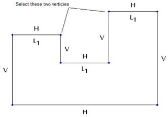
The result will be the following.

The little rectangle icons facing each other is the symbol for this constraint. These same rectangles will appear for the Collinear constraint when two lines are selected, but the icon for Aligned looks different.
If we turn the view of dimensions back on, we can see that we only have three dimensions left.

Compare that to the original sketch before we started adding constraints.
Because we are not allowed to over-dimension the model, the addition of constraints has forced many of the weak dimensions to disappear.
The following table shows the symbols that will appear for each type of constraint.
|
Constraint Type |
Symbol(s) |
|
Vertical Line / Line up Vertically |
|
|
Horizontal Line / Line up Horizontally |
|
|
Perpendicular |
|
|
Tangent |
|
|
Midpoint |
|
|
Collinear / Aligned |
|
|
Symmetric |
|
|
Equal Length / Radii |
|
|
Parallel |
|
Within the constraint window, there is a button called Explain. If you click on this button, then on any constraint symbol on the sketch, it will highlight the entities that are affected by that constraint, and in the message window, it will describe the condition that has been set.
For example, if you click on an L1 symbol, it will highlight two or more line entities, and the message window will say “Highlighted linear segments have equal lengths.”
TEXT TOOL
To create logos, part markings, and other text-type features on the model, you will probably have to sketch text at some point in time. This tool is used for that purpose.
To start creating text in your sketch, click on the icon shown below.
![]()
Then, sketch a line that represents the start of the text. The first point of the line that you pick represents the lower left corner of the text as it reads from left to right, as shown below.

The second point on the line represents the height and orientation of the text. If you sketch a vertical line straight up (as we see in the figure above), then the text will be readable from left to right.
If we sketch the line straight down, the text will be upside down and backwards. If you sketch a slanted line, then the text will be at an angle.
Once we sketch the line, we see a window appear that looks like the following.

In the top field, type in the words you want for the text. In the middle section, you can change the font used, the aspect ratio (the width of the word), and the slant angle (to control italics). You can use any True-Type fonts (like you might find in Microsoft Word). See your system administrator if you need a font added to the list.
The following figure shows text using CG Times (Times New Roman equivalent).
You can also get your text to follow a sketched curve (spline, arc, etc.) Suppose we want to have the text follow a three-point arc. We sketch the arc, then click on the text tool. The start point of our text will be at the left end of the arc, and we will sketch a line perpendicular to the arc (look for the perpendicular constraint symbol to appear as we sketch). Once we sketch the line, our text window appears, and we enter the text, but we notice the text is still perpendicular to the line that we sketched, as shown in the figure at the top of the next page.

In the text window, click on the Place Along Curve option, then select the arc. The text will automatically wrap around this arc. Use the Aspect Ratio slider to get the text to fit on the line. The result is shown below.

Once you finish, click on the green check mark to complete the text, then adjust the height of the text by modifying the dimension, or dragging the top end of the line that starts the text. To modify the text (get back to the text window), click on the modify tool icon, then pick on one of the letters.
TRIM TOOLS
If you click on the trim tool icon, you see the following trim options.
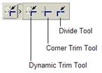
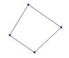
DYNAMIC TRIM
The dynamic trim tool is used to eliminate portions of the sketch you do not want to keep by clicking on the items or drawing a path through the items. Take the following sketch for an example.

Suppose we only want to keep the portion in the middle where all of the lines intersect. We would select the dynamic trim icon, then either pick on all of the outside portions of the lines one-by-one, or draw a path that goes through the outside sections at once, as shown below.
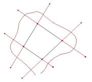
Once we are finished dragging the path around the part, let go of the mouse. The result will be as follows.
CORNER TRIM
The corner trim tool is both a trim for intersecting entities, or an extend for non-intersecting entities. For this tool, you want to select on the part of the entity that is going to remain after the trim. For example, look at the following sketch.
We want to connect up the two line segments (extend), and then trim away the small portion of the line that lies past the arc intersection. Therefore we would use the corner trim tool and select in the areas indicated in the following figure.

The resulting sketch after this trim will look like the following.

DIVIDE TOOL
The divide tool is used to break up a single sketched entity into multiple entities. You might use this when sketching for a blend feature, because the number of entities has to be equal. Therefore, if you were blending a circle to a square, the circle would have to be divided into four sections.
The following figure shows where you might pick on a line to divide it, and then its resulting sketch after the divide.

results in…
TRANSFORM TOOLS
Selecting on the transform tools icon gives you the following choices.
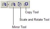
MIRROR
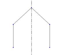
This tool is used to mirror selected entities about a sketched centerline. You always want to take advantage of symmetry in your models, and this is a great way to save time in sketch mode.
To use the mirror tool, select all of the entities you wish to mirror, click on the mirror tool icon, and then click on the centerline that acts as the mirroring plane. The following sketch is an example of how the mirror tool works.

results in…
SCALE AND ROTATE
This tool is used to resize, move and/or rotate an existing set of entities in the sketch. To use, select all of the entities you wish to affect, then click on the scale and rotate tool icon. Enter the appropriate scaling factor and/or angle, or dynamically drag these values on the screen.
To demonstrate this, look at the following sketch.
Using the select tool, we will drag a box around the entire sketch, and then click on the Scale and Rotate icon. The dimensions disappear from the sketch temporarily, and three symbols appear, as shown in the figure at the top of the next page.

Using the left mouse button, we can select once on any of these items then move the mouse cursor to see it dynamically change. Once we are done, click again with the left mouse button to place the entity at its new location/orientation/size.
At the same time we see these symbols, a window pops up in the upper right corner. It looks like the following.

We can type in a value for the scale factor or rotation angle. In this example, we will enter a Scale of 1.5, and a Rotate value of 45 degrees. Once we are done, we will click on the green check mark. Our sketch now looks like the following.
We can see that the dimensions are now 1.5 times larger, and the rectangle has been rotated 45 degrees. Since we don’t have any other entities in our sketch, a weak dimension had to be added to account for the rotation, and we can see this in the figure above.
COPY
The last transformation tool is the copy tool. To use this, select the entities you wish to copy, and then click on the copy icon. It performs a “Copy and Paste” operation right in the sketch, and the new copy will appear in the upper left corner of the sketch with the same symbols we saw in the Scale and Rotate tool.
Use the same techniques to move, scale or rotate the copied entities. To demonstrate this, look at the following initial sketch.

We want to make a copy of the inside closed set of entities. Therefore, we use the select tool, and we drag a box around these entities to select them. Once they are selected, we click on the Copy tool, and we can see a copy of these entities appear in the upper left corner, as shown in the following figure.

Using the dynamic move and rotate symbols, I will locate the copied entities the way I need them, as shown below.

Once they look the way I want them, I click on the green check mark in the pop-up window, and my sketch looks like the following.

ACCEPT / CANCEL
When we are finally done with our sketch, we will click on the accept icon, which looks like the following.
![]()
If we were in a sketch that was part of a feature creation method, such as an Extrude feature, then we would be placed in the next sequence of events for creating that feature. If we are in a stand-alone sketch and click on this icon, we are placed back out into the Pro/ENGINEER interface, ready to open a new file or activate an already open file.
To cancel out of a sketch, click on the following icon.
![]()
You will be asked to confirm the cancel of the sketch. If you accidentally cancel the sketch, it should still be in session memory, and you can simply open it again.
SKETCH MENU
So far, we have spent a great deal of time going over the sketcher toolbar. Many of these same functions are available in the Sketch menu, located in the menu bar. The sketch menu has a few functions, however, that are not icons. This section will talk about some of these.
CENTERLINE TANGENT
This tool creates a centerline tangent to two entities. Use Sketch, Line, Centerline Tangent from the menu bar to access this tool. Use the left mouse button to select the two entities that the centerline will be tangent to. The centerline will still span the entire sketch window. The following figure shows a sample centerline tangent entity.
AXIS POINT
An axis point is a sketched point that, when extruded, generates a datum axis on the model. We will learn more about datum axes later, but the following figure illustrates this.
Use Sketch, Axis Point from the menu bar to create this entity. NOTE: This only is available if you are currently sketching as part of an extrude feature, it does not work in stand-alone sketch mode.

AXIS OF REVOLUTION
When you create a sketch for a revolved feature, you must create a centerline that acts as the axis of revolution. By default, the first centerline that you sketch becomes the axis of revolution. If, by mistake, you realize that you didn’t sketch an axis of revolution, and you already have several centerlines on your sketch, you can use this feature to specify a different axis of revolution.
Click on the centerline that you wish to use, and then select Sketch, Feature Tools, Axis of Revolution from the menu bar to create this entity. The following figure illustrates this. NOTE: This also will not work if you are in a stand-alone sketch, it only works if you are in the sketch to create a revolved feature.

TOGGLE SECTION
When you create a parallel blend feature, you must sketch at least two different sections. Every section that you create is done in a single sketch. To tell Pro/ENGINEER which sketched entities belong to one sketch and which belong to another, we toggle between sketches.
To toggle between sections, go to Sketch, Feature Tools, Toggle Section from the menu bar. Again, this will only work if you are trying to create a blended feature, not in stand-alone sketch mode.
The current sketch is in the color of the sketched entities (yellow in Wildfire 2.0), while the inactive sketch becomes a muted gray color (similar to the weak dimensions). Suppose we want to blend between a circle and a rectangle. We might start by sketching the circle, then use Sketch, Feature Tools, Toggle Section. The circle becomes a muted gray color, and then we sketch the rectangle, which is still in the primary sketch color (in this guide that will be black). The following figure demonstrates this.
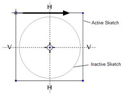
Using the Toggle Section command again will cause the circle to become the active sketch, and the rectangle will become the inactive sketch. We will see more of this when we get to the blend feature.
START POINT
In several features in Pro/ENGINEER, we must define a vertex that acts as the starting point of our sketch. We can see this in the figure above for Toggle Section. The bold arrow pointing towards the right from the upper left vertex is the symbol for a start point.
To change the start point, we select a different vertex on the sketch, and then use Sketch, Feature Tools, Start Point. The arrow will switch to that new vertex.
BLEND VERTEX
A blend vertex is used in the blend feature sketch to force multiple entity sections to converge into fewer entity sections. For example, blending a square into a triangle forces two corners of the square to converge into one corner of the triangle.
To specify which corner of the triangle will accept the two corners of the square, we select that vertex, and then use Sketch, Feature Tools, Blend Vertex. The blend vertex is represented by a larger circle around the vertex selected. The following figure shows the blend vertex and the start points for this example.

DATA FROM FILE
To re-use saved sketches, or to import neutral data into your sketch (such as IGES, DXF, Adobe Illustrator, Images, etc.) use Sketch, Data From File. This will bring up the following window.

Each data type that we bring in prompts us for different options, so we will only talk about inserting saved Pro/ENGINEER sections (.sec files). When you select the file you wish to bring in, it will look and behave exactly the same as the Scale and Rotate or Copy tools under the Transform icon.
Scale, move and/or rotate the sketch that you are bringing in, and then click on the green check mark in the pop-up window to place the sketched entities. Continue to add/remove from this sketch as necessary, and then accept it once you are done.
This is the way you will bring in the logo sections, part markings, recycle symbols, etc.
OPTIONS
The last item in the Sketch menu is the sketcher options or preferences. When you select this option, you will get the following window.
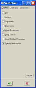
There are three tabs: Display, Constraints, and Parameters. On the display tab, we can toggle on/off the display of sketched entities. We can see that we currently do not have dimensions or constraints shown in our sketch.
The second tab, entitled Constraints, looks like the following.

In this section, you can disable automatic constraints while sketching. Right now, sketcher can assume any one of the above conditions if it looks like that is your intention. I would recommend exaggerating your sketch instead of turning off automatic constraints.
The third tab is the Parameters tab, which looks like the following.

At the top of this section, we can define the grid type, origin and angle. The default grid type is Cartesian, which creates an X-Y sketching grid. The other option is Polar, which can be used to help you sketch entities which predominantly lie around an axis normal to the screen.
In the second section, we can define the grid spacing. This only helps you if you turn on the display of the grid, and set the sketch to snap to grid. These settings are on the first tab.
In the third section, we can define the number of decimal places for our sketcher dimensions, and the relative accuracy of the sketch. This is useful if you are sketching very small entities in the same sketch where you have much larger entities. The smaller entities might appear to Pro/ENGINEER as having zero length. Increasing or decreasing this number may help fix sketch regeneration errors.
EDIT MENU
The Edit menu in the menu bar has some of the sketcher options, such as Modify and Trim. There is one additional item that is very important to discuss here. That is Replace.
REPLACE
If you are creating a model, and you sketch a feature, such as an Extrude. When you created the sketch, the single line entity in the sketch extrudes to form a surface that has an edge that lies on the sketching plane, and an edge that is projected to the depth location.
Both edges of this surface rely on the single sketched entity. If we add a round to one of the edges of this extruded feature, then that round now relies on that sketched entity (by way of the extrude feature).
If we were to go into the sketch again after we created the round, and deleted the entity that eventually made up the edge, then the round would fail. We can use the replace command to sketch a new entity and make the downstream features use it instead of the original one.
To do this, you would sketch a new entity. Once the entity has been sketched, you would select it so it becomes highlighted in red. Then you would use Edit, Replace. You will then pick the old entity that the new one replaces. You will probably be prompted to delete dimensions that were applied to the old entity. Re-dimension the new entity as needed, then finish out of the sketch. The features downstream should regenerate successfully.
The following figure shows the original sketch, extrude feature, and round for this example.

Now, suppose we want to make the following change.

When we go back into the original sketch, if we simply pick on the edge and hit the Delete key, we get the following warning in the message window.
![]()
This is letting us know that if we delete this entity, other features downstream will fail. We will click on No to the right of the message window to cancel the deletion of this entity.
Therefore, we will sketch the new arc that will soon replace the edge, as shown below.

The old edge is still in the sketch, because we can’t delete it just yet. Once we have the new arc sketched, we will click on it to highlight it in red, then go to Edit, Replace. We are prompted in the message window to select the old entity to replace. We will pick on the vertical edge. When we do, we get the following window.

You may or may not get this window, depending on how your sketch is dimensioned. If you are prompted with this window, do not worry. Click on Yes to delete any necessary dimensions, and then re-apply the necessary dimensions to the new arc. Once you are done, you r final sketch, extrude and round feature will look like the figure at the top of the next page.

We can clearly see that the Extrude and Round features are able to use this new arc. If we had deleted the edge and sketched the arc in its place, the round would certainly have failed. The extrude would not have failed, because it will successfully use any regenerated, closed sketch, and because the sketch was for this feature.
RIGHT MOUSE BUTTON
You will also find that most of the common functionality in Sketcher can be carried out using the right mouse button. Lines, arcs, circles, rectangles, as well as dimension and modify are a few of the items that show up on the screen when you click on the right mouse button. If you have an entity selected, you may get additional menu items. Feel free to use the right mouse button for easy and fast switching between common tools and functions.
LESSON SUMMARY
Many of the features in Pro/ENGINEER require a sketch of some sort. This lesson went into great detail to cover most aspects of sketching and sketch mode.
Remember to always sketch in the following order:
· Select References
· Sketch Quickly but Accurately
· Constrain Entities
· Dimension
· Modify Dimensions
· Accept Sketch
Make use of symmetry whenever possible and mirror your sketch to save time.
You can use the menus at the top, the icons in the sketcher toolbar or the right mouse button to access common sketcher commands and tools.
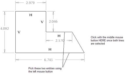
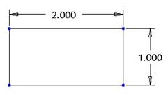
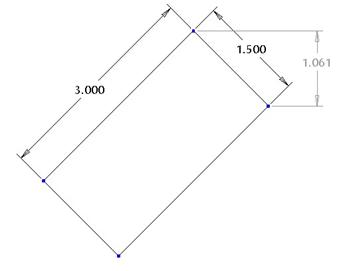
EXERCISES
Create the sketches shown on the following pages as stand-alone sketches. Be sure to follow the proper sketcher steps (with the exception of the “Select References” for these exercises. Save each sketch once you are complete before Accepting them.
Sketch 1 – Shear_Plate.sec

Sketch 2 – Latch_Plate.sec