Lesson 3

Lesson Objective: In this lesson, we will learn about action-object versus object-action selecting, query select, as well as pre-selecting.

ACTION-OBJECT / OBJECT-ACTION SELECTING
Some of the features in Pro/ENGINEER are created by selecting on an action first (Insert, Blend, Surface, for example), then later you select your references, such as curves, planes, etc.
In Pro/ENGINEER Wildfire 2.0, most of the common feature types can also be created using an Object-Action method of selecting. For example, to create a surface copy, you would have to select your surfaces first, then click on the copy icon.
In order to make Object-Action selecting easier, there is a Pre-Selecting function that allows you to see a preview of the geometry you are going to select before you select it.
PRE-SELECTION
As you move your mouse over a model in the working window, you will see objects highlight in blue. When you move your mouse past the object, the highlight disappears, and a new one appears at the next location. This blue highlighting is called Pre-Selection.
If you leave your cursor over a highlighted object long enough, a tool tip will appear showing you the feature that is currently highlighted. In the following figure, we can see a protrusion highlighted.

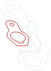
With the highlight visible on the feature or geometry we want to select, we use the left mouse button to click on that object. The object will turn red, which indicates that it has been selected, as shown below.
To remove any selections you may have made, click anywhere outside of the model in the working window.
SELECTION FILTER
During pre-selection highlighting, you may see only features highlighting. This is due to a filter that is applied by default, called Smart. We can see the selection filters in the lower right corner of the Pro/ENGINEER interface, as shown below.
![]()
The smart filter performs a “Drill Down” approach to selecting. You begin by selecting features (Protrusions, Cuts, Drafts, Rounds, etc.), then you pre-select geometry, such as surfaces, edges, vertices, etc.
If we click on the pull-down arrow in this field, we can see the other filters that can be applied.

The other, different filters are:
· Features – only features will be selectable.
· Geometry – only geometry (surfaces, edges, etc.) will be selectable.
· Datums – only datum geometry (planes, axes, points, curves, etc.) will be selectable.
· Quilts – only surface quilts will be selectable
· Annotation – only notes, geometric tolerances, etc. will be selectable.
For example, if we change our selection filter to Geometry, then place our mouse over the same protrusion as we did before, we will only see a surface pre-select highlight, as shown in the figure below.

Then, if we click with our left mouse button to select the surface that is highlighted, we see something slightly different than what we saw when we selected the protrusion before.

A surface, when selected, will shade or mesh, depending on what view display you have set. In No Hidden, Hidden Line and Wireframe, the selected surface will mesh, as we see in the figure above. In Shaded mode, the entire surface will shade a rose color, as we can see in the following figure.

For the remainder of this training guide, we will only show figures in a non-shaded mode (unless it is necessary for clarification to show it in shaded mode). This is due to the ability for you to see these figures when reproduced on a black & white color copier.
QUERY SELECT
Often times, what we want to select is not at the front of the model in the current orientation. Instead of rotating the model around every time we want to select hidden geometry, we can use a tool called Query Selection, which allows us to query through possible objects until we see the one we want in a pre-selection highlight (blue highlight).
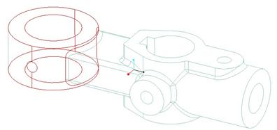
For example, suppose I want to select the two surfaces of the hole indicated below.

If I have my selection filter set to Geometry, and place my cursor over the hole, I can see that the back half of the hole can be picked without querying through the possible choices, as shown below.

Now, I want to pick the other half. The first thing I need to do is hold down the Ctrl key on my keyboard to select multiple objects. When I place my mouse cursor over the end of the hole, only edges highlight in blue. I could zoom in or rotate and get a clear view of the other half of the hole, but that would defeat the point to this discussion.
Instead, I am going to place my mouse cursor over the model in an area that is in front of the surface that I want to select. Imagine if the mouse cursor were a drill bit going into the screen of the computer and into the model in its current orientation. You want to place your cursor over the model so that as you “drill” down into the part, you come in contact with the object you want to select.
The figure at the top of the next page shows a possible location that clearly sits in front of the surface that we ultimately want to select.

Since the outside surface of the protrusion is in front of our hole, only the protrusion surface highlights initially, as we can see in the figure above.
To query through the possible choices, click on the right mouse button (remember to keep the Ctrl key pressed to select multiple objects). A single click results in the hole surface highlighting, as shown below.

Now that the surface we want to select is highlighted in blue, we can click with the left mouse button to select it, as shown below.

REMEMBER! – Even though we are working in a non-shaded mode, we still have surfaces on this model. To select a surface, you want to pick out in the middle of the surface and not near its edges, otherwise you might select an edge instead.
This is one of the biggest mistakes new users make that come from 2-D or other drawing packages. The following figure shows the correct and incorrect place to pick for selecting a surface.

EDGE SELECTING
Using the same selecting techniques, we will talk about selecting edges. To start with, you can select a filter, such as Geometry, which will allow you to pick just edges, surfaces, etc. Then, bring your mouse over the edge to select. As with surfaces, it will pre-highlight in blue, as shown below.

When you click with the left mouse button, the edge becomes selected, as indicated by a bold red highlight, shown below.

You can hold down the Ctrl key to select multiple edges independently, however we are going to demonstrate how to pick edge chains. If you hold down the Shift key, then move your mouse cursor over to a different edge (in this case, on the same surface), we will see different objects highlight, as shown below.

The first thing it looks for is any tangent chain of edges to the one we originally selected. From the figure above, we can see that there are four other edges (two straight edges at either end, and two circular edges around the corners) that connect up to the first selected edge to form a tangent chain of edges. The Tool Tip indicates Tangent.
If we query select (click with the right mouse button), we will see another possible option for edges, which in this case is the entire set of edges that go around the top surface (connected to the edge that we previously selected). The tool tip indicates Surface Loop, as shown below.

Click again with the right mouse button, and we will see a From-To surface loop starting from the selected edge and going around the top surface boundary until it gets to the edge our mouse is currently over, as shown below.
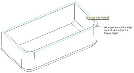
Click one more time with the right mouse button, and we see the opposite surface loop condition (going the other direction around the top surface boundary).

If this were the set of edges we wanted, we could now click with the left mouse button to select it (remember, we are still holding down the Shift key on the keyboard.)

SEED AND BOUNDARY SURFACE SELECTING
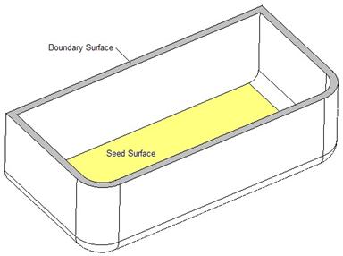
One last method of selecting is to get all of the surfaces between two boundary surfaces. One of the boundary surfaces actually lies within the set of surfaces to be selected. This is known as the Seed surface.
The other surface lies at the external end of the surfaces to be selected, and is called the Boundary surface.
The following figure illustrates the seed and boundary surface you would select to get all of the internal surfaces of our cavity.
Therefore, we will begin by selecting the seed surface, as shown in the following figure.

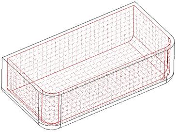
Next, hold down the Shift key and select the top surface of the part (the Boundary surface). While the Shift key is still depressed, you should see the following.

Once you let go of the Shift key, the proper surfaces will be selected, as shown in the next figure.
The Boundary surface is never selected, only the Seed surface and all of the other surfaces between the seed and the boundary. To select additional surfaces at this point, use the Ctrl key. To deselect any of the selected surfaces, also use the Ctrl key and select the surfaces to exclude. For example, selecting the back surface with the Ctrl key gives us the figure at the top of the next page.

A RUNNING TOTAL
Within the selection filter area, we will see some text indicating how many objects are currently selected. For example, if we were to select the following surfaces and edges using the Ctrl key, we would have 8 items selected.

In the selection filter area, we see text that says 8 Selected, as shown below.
![]()
If you double-click on the actual text, it opens up the window shown at the top of the next page.

As you move your mouse over this list, the items will highlight in blue on the model itself. You can remove any unwanted selections by selecting them in this list, then clicking on the Remove button at the bottom.
LESSON SUMMARY
Many of the features in Pro/ENGINEER use an object-action method of selecting, or selecting the surfaces or edges that you are going to act upon, then pick the feature to create, such as picking on an edge, then picking the round tool.
You can pre-highlight objects before selecting them. This makes it easier to know what you are going to pick. Use the selection filter in the lower right corner to pick only on the types of objects you want.
Use Query select to drill down into the model to pick hard to reach items, or to scroll through a set of possible edge chain options.
Finally, use the Shift key to perform Seed and Boundary or Edge Chain selecting, and use the Ctrl key to pick many individual items.
EXERCISES
Open up the Idler_Arm part file and go to a default view. Using techniques learned in this lesson, try selecting all of the edges that touch the front face of the part, as shown in the following figure.
Next, use whatever method you want to select the following surfaces (NOTE: This can be done with a seed and boundary if you pick the right combination of surfaces).

Close out of this model when done, and erase session memory.