Lesson 2

Lesson Objective: In this lesson, we will learn about the User Interface of Pro/ENGINEER Wildfire 2.0, file operations, viewing modes and how to spin, pan and zoom in this release.

STARTING Pro/ENGINEER
Pro/ENGINEER Wildfire 2.0 is installed in the C:\ptc\proewf2 directory. On your desktop, you will find the following shortcut.

When Pro/ENGINEER launches, it will start in the following directory.
C:\Data\proewf2
Every time you open up a new session of Pro/ENGINEER, a file is created that captures every command, menu pick, and operation you perform. This file is called a trail file, and it is created and stored in your C:\Data\trails folder. Trail files can be used (with some limited degree of success) to restore work that is lost if you crash out of Pro/ENGINEER without having saved, however most of the time, this is not successful.
Trail files do not need to be saved. Since they take up some disk space, it is recommended that you clean out your c:\trails directory from time to time.
USER INTERFACE
Once you launch Pro/ENGINEER Wildfire 2.0, you will see the following user interface.
The following figure shows the different components of this interface when a model is opened.
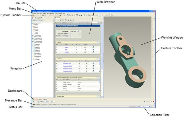
The Wildfire 2.0 interface is made up of the following main areas (from top to bottom and left to right):
· Title Bar – Lists the currently object, and indicates whether the object is active.
· Menu Bar – Every command in Wildfire 2.0 can be accessed from the menus at the top of the application.
· System Toobar – Contains icons that control system-wide functions, such as the file operations, model display, datum display, window controls, etc.
· Navigator – Contains several different tools used to navigate through the model or the interface, such as the model tree, layers, file explorer, favorites, and web browser controls.
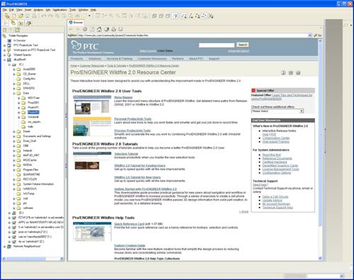
· Web Browser – This is a fully functional web browser. Upon the initial startup of the application (or by clicking on the home icon), you can get to a web page with helpful information regarding this release. It also doubles as an information window for various tools in the software, such as a feature information window, bill of material reports, and when you click on a folder in the file explorer, it shows the contents in this browser.
· Working Window – This is the main working area in Pro/E. Your geometry or drawing will appear in this window, and you select and build features in this area.
· Feature Toolbar – Contains icons used to create or edit geometry. These are context-sensitive, which means that as you are in a specific function, you will see additional or fewer icons.
· Dashboard – Appears in most of the common feature creation modes. Contains options and elements for defining features.
· Message Bar – Area where information is displayed in the form of prompts, warnings, general information, etc.
· Status Bar – Provides additional information if necessary. It also displays the tool tip when the mouse is placed over an icon, menu or geometry in the main working window or in any of the other toolbars.
· Selection Filter – Used to select different filter options for picking. Displays the total number of selected objects.
COLOR SCHEME
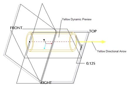
Every command or function in Wildfire 2.0 that displays graphically will have a different color associated with it. For example, when you move your mouse over a model, you will see geometry highlight in blue. Once you select geometry, it turns red. As you create features, you will see a yellow preview of the geometry. Datum planes have a positive brown side and a negative black side, etc.
For the purpose of being able to clearly print and read this training guide on most Black & White LaserJet printers, most of the system colors will not appear in the pages of this booklet. We will clearly describe colors that you should see at the time you should see them, so you should be able to follow along very easily. The following figure describes the convention that we will use for this guide.
FILE OPERATIONS
SET WORKING DIRECTORY
If you recall from the first section of this lesson, we mentioned that Pro/ENGINEER Wildfire 2.0 starts up in the C:\Data\proewf2 folder. You can change over to any folder on your computer after you open up the software. The folder that you change to is called the Working Directory. If you choose not to change over to a new folder, then the start up directory is the working directory.
To change your working directory, there are three ways to do this. Using the menu bar, go to File, Set Working Directory, or click on the following icon in the system toolbar.
![]()
With either of these options, you will get a new window that appears, as shown below.

In this window, select the folder you wish to use as a working directory. You can use the Directory Pull-Down to switch to a folder or network drive, use the Up One Level icon to go up one folder level, or you can even create a new folder in the current location using the Create New Folder icon.
Once you have selected or created the working directory folder, click on OK.
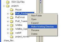
The third way to set your working directory is to go to your Navigator and access the file explorer. Find the folder that you want to work out of, then hold down the right mouse button over that folder and select Make Working Directory, as shown in the following figure.
OPEN FILES
Opening files in Pro/ENGINEER is the same as in any windows application. Either go to File, Open from the menu bar, or select on the following icon from the system toolbar.
![]()
You will get a window that is very similar to the one you saw when setting your working directory, as shown below.

Initially, all Pro/ENGINEER items (parts, assemblies, sections, drawings, formats, etc.) will show up in the window for the current directory that you are in. If you want to apply a filter to only see part files, use the Type Filter pull-down towards the bottom of the window.
If you are browsing through other folders and wish to return to the current working directory to look there, click on the Working Directory icon. To browse through favorite locations that you set up, click on the Favorites icon.
You can also change the display type using the Change Display Options icon. This would allow you to see a list, or icons, or details, etc.
In Session Memory
Every time you open up a file in Pro/ENGINEER, it gets stored into memory. This is called Session Memory. The item does not have to be open to remain in memory. To view what is currently in memory, go to the open file window, and click on the In Session Memory icon (shown above). Only items that are in memory will be listed.
Preview
To see what the object looks like before opening it, you can click on the Preview button in the lower right portion of this screen. It will expand the window open to the right, and you will see the file, as shown in the figure at the top of the next page.
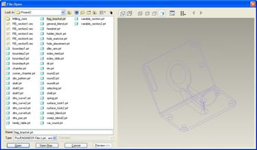
Once you find the file you want, either double-click on it using the left mouse button, or click on it once to highlight it, then click on the Open button in the lower left of the File Open window.
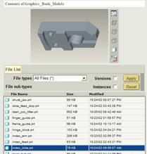
Another way you can open a file in Pro/ENGINEER Wildfire 2.0 is to go to your file explorer in your Navigator, locate the folder that contains your file, and click on that folder once with the left mouse button. The contents of the folder will appear in the Web Browser, as shown below.
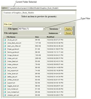
To preview the geometry before opening it, click once on the file in the File Names column. The preview appears at the top of the screen as shown at the top of the next page.
To open the file, either double-click on it using the left mouse button, or drag the file from this list out to the Working Window.
ERASE
As we mentioned previously, once you open up a file in a current session of Pro/ENGINEER, it remains open until one of two things happens.
· You exit the application using File, Exit.
· You erase the object from memory.
Simply closing the file will not erase it from memory. To erase a file, go to File, Erase from the menu bar. You will see two options for erase. These are:
· Current – Open erases the active file from memory (next topic).
· Not Displayed – Erases all objects that are not currently open.
EXAMPLE:
Suppose you open three part files, A.prt, B.prt and C.prt. All three files are currently in session memory. If you were to close part B, it is still in memory. If C were the active model, and you used File, Erase, Current, then C (and only C) would be closed and erased from memory. If you used File, Erase, Not Displayed, then B (and only B) would be erased from memory. A and C would remain open and in memory.
ACTIVATE OBJECT
The object you are currently working on is considered the Active object. You can have as many files open at the same time, but only one can be active at any time. To activate an object, go to Window from the menu bar.
At the bottom of this menu, you will see a list of currently open objects, as shown below.
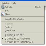
The object that has the black circle to the left of it (currently shown as the CROSS_FEED_STOP.PRT file in the figure at the bottom of the previous page) is the active model.
To activate a different model in this list, simply select it from the list at the bottom. To close a file, it must be the active file, then you can use Window, Close or File, Close Window from the menu bar.
If you were to open a file at this point in time, it will become the active model automatically. You might notice that you have icons in your Windows Start Bar on your desktop for each of the objects that are currently open in Pro/ENGINEER.
If you were to select the icon in this Start Bar, it will bring that object to the front of the Pro/ENGINEER interface, but it does not automatically make that model active. You can activate it by going to Window, Activate from the menu bar once the file is in the foreground.
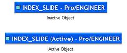
You will be able to tell if the currently visible object is active by looking at the title bar in the upper left corner. The following figure illustrates an active and inactive object indicated by the title bar.
SAVE FILES
To save the current file, go to File, Save or click on the following icon in the system toolbar.
![]()
In the message window, you will be shown the part that is being saved. Click on the Enter key on the keyboard, or the green check mark to the right of the message window.
File Versions
Most Pro/ENGINEER files append a number at the end of the file extension – filename.prt.1 for example. Every time you save that object, a new file will be created with the next higher integer – filename.prt.2 in this case.
Your working directory will start to fill up with versions of the same file. For example, if you create a new part called mypart, and save it for the first time, you would see the following in your working directory.
mypart.prt.1
As you continue to work with this part, you will save often. By the end of the day, you may have saved this part 10 times, and so you would see the following in your working directory.
mypart.prt.1 mypart.prt.3 mypart.prt.6 mypart.prt.9
mypart.prt.10 mypart.prt.4 mypart.prt.7
mypart.prt.2 mypart.prt.5 mypart.prt.8
You will notice that, sorted by name, the .10 file comes right after the .1 file. Be aware of this if you decide to manually delete older versions.
DELETE FILES
Before you delete any Pro/ENGINEER files, be absolutely sure that no other Pro/E files are dependent on the files you wish to delete. For example, suppose you created an assembly and used a particular component. If you delete this part before you take it out of the assembly, then the assembly will fail when you try to open it.
To delete a Pro/ENGINEER file (part, assembly or drawing), the best way to do this is to go to the menu bar and select File, Delete. When you do this, you will see two options.
· Old Versions – Delete all of the versions from the hard drive except the most recent for the currently active file. This method purges old versions but leaves the most recent in memory.
· All Versions – Delete all versions of the file from the hard drive, including the most recent, and erase the current file from memory. This is a total loss of data for this file.
It is not recommended that you blindly delete files from your hard drive through a windows explorer unless you really know the relationships. It is recommended that you purge your working directory once you are satisfied with the most recent version of the file that you are working on. This will free up disk space.
SAVE A COPY
This command is used to do one of the following:
· Make an exact copy of the current object with a new name.
· Export the file into a different file type (such as IGES, STEP, STL, etc.)
With the current object open, go to File, Save A Copy from the menu bar. You will see the following window.
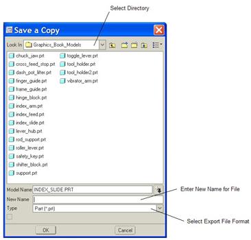
To make an exact copy with a different name, first select the directory where the file is going – or leave this step out to make the copy to your current working directory. Then, enter a name in the New Name field. Once you are done, click on OK.
To export the model as a different file type, first select the directory where the file is going – or leave this step out to create the new file in the current working directory. Then, use the Type pull down to find the file type that you wish to create (IGES, for example). The name should appear automatically in the New Name field with the appropriate extension added. Click on OK to complete the file export.
BACKUP
The backup command creates the exact file that you are working with, but in a different directory. The difference between a Backup and a Save A Copy is that a Backup allows you to keep the same name, but Save a Copy forces you to specify a different name.
The backup command is really useful if you need to make a duplicate copy of an entire assembly, because it copies the assembly and all of its components to the directory you specify.
To perform a backup, go to File, Backup from the menu bar. You will get the following window.
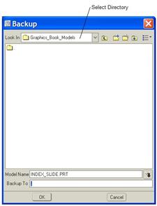
Click on OK to complete the backup operation.
RENAME
You must really be aware of relationships when renaming in Pro/ENGINEER. NEVER rename a part using a windows explorer, always rename through Pro/ENGINEER.
When you rename a part file, you must have any assembly and/or drawing file also open. If you do not, then the assembly or drawing will still be looking for the old file name when it tries to open, and when it doesn’t find it, it will fail.
To rename the currently active file in Pro/ENGINEER, use File, Rename. This will bring up the following window.
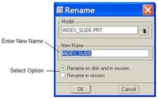
Enter a new name for the file in the New Name field, then select the option below this. There are two options:
· Rename on disk and in session – renames the file in memory, and renames it on the hard drive (for all versions that exist). This is the preferred option for most renaming operations.
· Rename in session – renames the file only in memory.
There are only two reasons why you might want to rename in session only. The first is if you accidentally renamed a part, and forgot to open the drawing or assembly file that uses it, then you could rename the part to the old name temporarily in memory to allow the assembly and drawing to open up, then rename it back to the new name once those files are open. The net change would be zero for the part.
The other case would be if you wanted to perform a “Save A Copy” type of command. If you rename the current file in memory only, then save it, it creates a new file in the working directory. This might be useful if you already made changes to an existing file, then realized that you forgot to save a copy of it first. By renaming it in memory then saving it, you left the original file at its last save.
The proper order of operations should be followed when performing a rename on disk and in session.
1. Open up the object to rename.
2. Open up all drawing or higher level assemblies where this object reports.
3. Rename the object then save it.
4. Change over to one of the other files (drawing or assembly) where the object reports and verify that the name has been changed for these files, then save them.
5. Repeat step 4 for every drawing or assembly file that contains the renamed object.
6. Close all objects and erase session memory (not displayed).
7. Retrieve each file to make sure the rename was successful.
NEW FILES
To create a new file in Pro/ENGINEER, go to File, New from the menu bar, or click on the following icon in the system toolbar.
![]()
This will bring up the figure at the top of the next page.
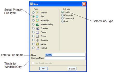
In this window, start by selecting the primary type of file being created (Part, Assembly, Drawing, Sketch). Our Pro/ENGINEER license only permits the following primary types to be created:
· Sketch
· Part
· Assembly
· Drawing
· Format
· Report
· Layout
· Markup
Once you select the primary object type, the Sub-Type options will change to reflect possible choices. In the figure above, we can see the sub-types for a part file. Select the appropriate choice.
Finally, enter a name for the file. Always remember to do this so you can avoid a rename condition later. Once you are done, click on OK to continue. You will now see the following figure.
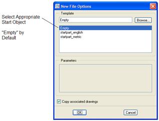
For this next window, the template should automatically select one of the following:
· Startpart – if you selected Part for the primary type, and Solid for the sub-type.
· Sheetmetal – if you selected Part for the primary type, and Sheetmetal for the sub-type.
· Startassy – if you selected Assembly for the primary type, and Design for the sub-type.
If you selected Drawing for the primary type, there are no sub-types. We will talk about all of these in more detail starting in the next chapter.
VIEWING MODES
There are four primary viewing modes in Pro/ENGINEER for Parts and Assemblies. To select a viewing mode, pick one of the following icons in the system toolbar:
·
![]() Shaded – All external surfaces of the
model are rendered and all hidden edges and surfaces will not be visible.
Shaded – All external surfaces of the
model are rendered and all hidden edges and surfaces will not be visible.
·
![]() No Hidden – All external edges of the model
are shown in the primary model color, but all hidden edges and surfaces will
not be visible.
No Hidden – All external edges of the model
are shown in the primary model color, but all hidden edges and surfaces will
not be visible.
·
![]() Hidden Line – All external edges of the model
are shown in the primary color, while all hidden edges are displayed in a muted
color.
Hidden Line – All external edges of the model
are shown in the primary color, while all hidden edges are displayed in a muted
color.
·
![]() Wireframe – All edges of the model (external
or hidden) are shown in the primary color.
Wireframe – All edges of the model (external
or hidden) are shown in the primary color.
The following figure shows the four different viewing modes for a part file.
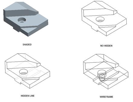
Shaded mode requires the least amount of time to display, and provides the best results for spinning. Wireframe is the second fastest in terms of display and spin, but is the least user friendly from a viewing standpoint.
MOUSE CONTROLS (SPIN, PAN & ZOOM)
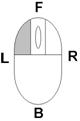
LEFT MOUSE BUTTON
 |
· Stand-alone, it is used to select/deselect objects
· Ctrl + = Select/deselect multiple objects
· Shift + = Select Seed and Boundary or Chain of objects
RIGHT MOUSE BUTTON
 |
· Context sensitive commands when held down
· Click to “Query Select” through model where mouse pointer is located
· Shift + = When selecting, it queries through multiple choices for the selected object. For example, when a single edge is selected, it will go through one-by-one, tangent chain, from-to chain, etc.
MIDDLE MOUSE BUTTON (Standard Mouse)
· Used to accept selections or finish commands when clicked
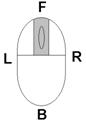 |
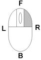
3D Modes
· Used to spin the model when dragged in all directions
· Ctrl + = Zoom In/Out (drag mouse in front [F] or back [B] direction) or Turn (drag mouse in Left [L] or right [R] direction – snaps to 90 degree locations).
· Shift + = Pan when dragged in all directions
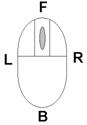
2D Modes
· Used to pan when dragged in all directions
· Ctrl + = Zoom In/Out (drag mouse in front or back direction)
MIDDLE MOUSE BUTTON (Wheel Mouse)
 |
Same functions as regular middle mouse, PLUS…
· By itself, it does quick zooming in and out when wheel is rolled Front or Back
· Ctrl + = 2X Quick Zoom speed (for rapid zoom).
· Shift + = 0.5X Zoom Speed (for slower zoom).
When spinning the model, you have two different ways to control the spin using the spin center. The spin center on/off control is located in the system toolbar, and it looks like the following.

When the Spin Center is turned ON, Wildfire 2.0 will always spin about the spin center, usually located at the geometric center of the model. This is the easiest spinning method to use, but does not give much control when you are zoomed into the model.
When the Spin Center is turned OFF, Wildfire 2.0 will spin about the location of your mouse cursor at the time you press down the middle mouse button/wheel. This allows for more control of the spin, especially when zoomed in close enough that the spin center is off the screen.
VIEW ORIENTATIONS
In addition to being able to spin, pan or zoom using the mouse and keyboard, you have other ways to control the orientation of the model on the screen. This section will discuss these different methods.
SAVED VIEWS
Built into the start part or start assembly, there are pre-defined saved views. These are FRONT, BACK, TOP, BOTTOM, LEFT, RIGHT, ISOMETRIC and TRIMETRIC. These views were created so the positive side of the default datum planes (which we will talk about in lesson 6) faces in the orientation of its name. For example, the FRONT datum plane’s positive side faces the FRONT orientation. The FRONT datum plane’s negative side faces the BACK orientation.
To access saved views, click on the following icon in your system toolbar.
![]()
It will expand to show the views that are available to pick on, as shown below.

DEFAULT VIEW
The default view is a system-defined view that exists for all models, even if there are no other saved views. Many times in Pro/ENGINEER, you will return to a default orientation to make seeing or selecting easier. To go to the default view, click on the following icon from the system toolbar.
![]()
PREVIOUS VIEW
To toggle between the current orientation and the last orientation, click on the following icon in the system toolbar.
![]()
RE-ORIENT
To create new orientations, click on the re-orient tool in the system toolbar (the icon shown below).
![]()
This will bring up the following window.
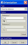
The default type of orientation type is Orient by Reference. The goal in this section is to pick two planar surfaces or datum planes that are perpendicular to each other and face them towards specified directions. Once you enter into this tool, you are automatically asked to select the first reference, as we can see in the figure above. Using the pull-down, we can change the direction the first reference will face. In this case, the first reference will face the Front (or face the screen).
Look at the following figures to see an example of using this tool. Start by selecting the first reference and its resulting orientation.

Once you select the first reference, it will appear in the field to the right of the selection arrow. Next, select the orientation and reference for the perpendicular direction. In the next figure, we will chose to face our reference towards the right, therefore we will select the right side of the model, as shown below.
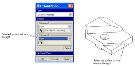
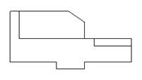
If the two references we selected are perpendicular to each other, the model should snap to its new orientation, as shown below.
In addition to selecting references to re-orient our model, we can dynamically control the spin, pan and zoom of our model by using the pull-down at the top of this Orientation window, and selecting Dynamic Orient. This will change the window to look like the following.
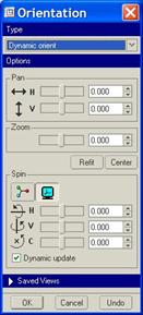
In the top portion, we can control the Pan of the model on the screen. In the second section, we can contrl the Zoom, and in the third section, we can control the Spin. Use the sliders or type in exact values in the spaces provided.
Under the Spin portion, you can select whether you are spinning about the spin center or about the screen center.
Down at the bottom of the Orientation window, you can also access the Saved Views functionality. Click on the blue bar where the name Saved Views appears to expand or collapse it. Expanding it will show the following.

You can double-click on any of the pre-existing orientations to set the model to that orientation, or type in a new name in the Name field, then click on Save to create additional saved views.
The last option at the top of this window is to change preferences for the re-orient tool. When you select Preferences you see the following.
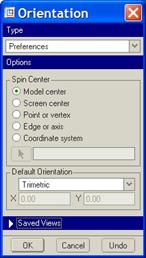
At the top of this window, select where the spin center will be. By default it is located at the model center (geometric center of the model).
In the lower window, you can specify which orientation will be used for the default view.
MISCELLANEOUS
When printing in Pro/ENGINEER, use one of the three non-shaded modes for printing parts or assemblies. To print, go to File, Print from the menu bar, or select the following icon on the system toolbar.
![]()
This will bring up the following window.
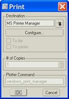
The first thing you want to do is select the printer that you are going to print to. Do this by selecting on the down arrow at the top, as shown in the following figure.
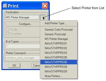
This list of printers is defined using Plotter Configuration Files (PCF). If you do not see a printer listed that should be listed, please contact your system administrator. Once you select your printer, the rest of the options on the Print window will become active. To change any of the print job settings, click on the Configure button, which will bring up the configuration for the current printer selected, as shown below.
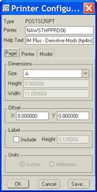
There are three tabs on this window. Within this section, you can select paper size, orientation, print zoom options, etc. The PCF files should be set up to use the optimal print settings for the printer, including the correct paper size. You should not have to change any settings in this window for most print jobs.
ZOOM CONTROLS
In addition to the dynamic orient and mouse controls, you have a few additional options for zooming on the system toolbar. These are:
·
![]() Window Zoom –
Click the opposite corners of a box around any object you want to zoom in on.
Window Zoom –
Click the opposite corners of a box around any object you want to zoom in on.
·
![]() Zoom Out – Each
time you select this icon, it will zoom out a small amount.
Zoom Out – Each
time you select this icon, it will zoom out a small amount.
·
![]() Refit – Zooms
out/in until all objects are visible and centered in the working window. This
does not work if you are in a sketch for the first feature of the model.
Refit – Zooms
out/in until all objects are visible and centered in the working window. This
does not work if you are in a sketch for the first feature of the model.
REDRAW (REPAINT/REFRESH)
Occasionally, you will need to redraw your screen to eliminate any graphical blips or ghost images, etc. This is also referred to as repaint or refresh. To redraw your screen, click on the following icon in the system toolbar.
![]()
LESSON SUMMARY
When you start Pro/ENGINEER, you will be placed into a working directory. Change over to the working directory you wish to use then start working.
When you save a file in Pro/ENGINEER, new versions of the file will appear in your working directory. Use Delete, Old Versions to purge all versions except the most recent.
If you must rename a file in Pro/ENGINEER, always make sure that any required files are also open and in session. Start renames with the lowest level object (Part Files), then rename assemblies, then drawings. Remember to save as you go.
To save session memory, erase non-displayed objects once you have saved and closed them.
The middle mouse button (MMB) is used for spinning when used by itself. Use Ctrl with the MMB to zoom, and Shift with the MMB to pan.
You can select from pre-existing saved views, or re-orient the model to create your own saved views.
There are four viewing modes. Shading is the best for spinning, panning, zooming and visualizing the model. Hidden line and No Hidden take longer to display.
EXERCISES
Once Pro/ENGINEER is opened, set your working directory to C:\Data\ProETrain.
Click on this folder in the file explorer (navigator) to see the contents. Click once on the Idler_Arm.prt part file to see the preview in the web browser. Try spinning the model in the preview window.
Place your mouse over the icon to the left of the Idler_Arm part file and drag it into the working window to open it.
Inside the working window, try spinning, panning and zooming using the mouse and keyboard controls. Once you are done, go back to a default view. Try looking at the different display modes. Use the Saved Views icon to go to a FRONT view.
Close the model but don’t exit out of Pro/ENGINEER. Use File, Erase, Not Displayed once the file is closed to erase session memory.