Appendix A

Appendix Summary: In this Appendix, we will see the solutions to all of the exercises for this training guide.
Lesson 1 _________________________________________________________ A-2
Lesson 2 _________________________________________________________ A-2
Lesson 3 _________________________________________________________ A-4
Lesson 4 _________________________________________________________ A-8
Lesson 5 _________________________________________________________ A-33
Lesson 6 _________________________________________________________ A-38
Lesson 7 _________________________________________________________ A-45
Lesson 8 _________________________________________________________ A-47
Lesson 9 _________________________________________________________ A-59
Lesson 10 _________________________________________________________ A-62
Lesson 11 _________________________________________________________ A-64
Lesson 12 _________________________________________________________ A-80
Lesson 13 _________________________________________________________ A-87
Lesson 14 _________________________________________________________ A-96
Lesson 15 _________________________________________________________ A-101
Lesson 16 _________________________________________________________ A-107
Lesson 17 _________________________________________________________ A-113
Lesson 18 _________________________________________________________ A-117
Lesson 19 _________________________________________________________ A-121
Lesson 20 _________________________________________________________ A-130
Lesson 21 _________________________________________________________ A-132
Lesson 22 _________________________________________________________ A-137
Lesson 23 _________________________________________________________ A-140
Lesson 24 _________________________________________________________ A-143
Lesson 25 _________________________________________________________ A-143
Lesson 26 _________________________________________________________ A-145
Lesson 27 _________________________________________________________ A-147
Lesson 28 _________________________________________________________ A-150
Lesson 29 _________________________________________________________ A-150
(Continued on Next Sheet)

Lesson 30 _________________________________________________________ A-153
Lesson 31 _________________________________________________________ A-154
Lesson 32 _________________________________________________________ A-158
Lesson 33 _________________________________________________________ A-163
Lesson 34 _________________________________________________________ A-163
Lesson 35 _________________________________________________________ A-166
Lesson 36 _________________________________________________________ A-166
Lesson 37 _________________________________________________________ A-166
Lesson 38 _________________________________________________________ A-179
Lesson 39 _________________________________________________________ A-179
Lesson 40 _________________________________________________________ A-189
Lesson 41 _________________________________________________________ A-189
Lesson 42 _________________________________________________________ A-189
Lesson 43 _________________________________________________________ A-189
Lesson 44 _________________________________________________________ A-189
Lesson 45 _________________________________________________________ A-189
Lesson 46 _________________________________________________________ A-189
Lesson 47 _________________________________________________________ A-189
Lesson 48 _________________________________________________________ A-189
Lesson 49 _________________________________________________________ A-189
Lesson 50 _________________________________________________________ A-197
Lesson 51 _________________________________________________________ A-197
Lesson 52 _________________________________________________________ A-197
Lesson 53 _________________________________________________________ A-197
LESSON 1 – Pro/ENGINEER Basic Elements
There are no exercises for this lesson.
LESSON 2 – Taking a Look Around
Set Working Directory
The first part of this exercise is to set your working directory to C:\Data\ProETrain. There are three different (and equally preferred) ways to do this.
Using the Navigator
Using the navigator, locate the folder that we want to switch over to. If you are not in the file explorer portion of the navigator, click on the following icon at the top of the navigator.
![]()
Once you find the ProETrain folder, hold down the right mouse button over this folder to see the available options, as shown below.

As indicated above, select the Set Working Directory menu option.
Using the System Toolbar
A second way to select your working directory was to click on the following icon in the system toolbar (the row of icons across the top).
![]()
This brings up a separate window, entitled Set Working Directory, and looks like the figure at the top of the next page.

Use the pull-down field in the upper left of this window to start your search, and then select the ProETrain folder in the main portion of this window. Click on OK to finish.
Menu Bar
The third way to set your working directory uses the menu bar at the top of the Pro/ENGINEER window. We would select File, followed by Set Working Directory, as shown below.

This brings up the same window shown previously. Select the folder, and then click on OK to finish setting the working directory.
Spinning, Panning and Zooming the Model
To spin the model, use the middle mouse button all by itself. Hold down this button and keep it held down during the duration of the spin, then release to stop the model in its new orientation.
To zoom the model, hold down the Ctrl key on the keyboard and then press and hold the middle mouse button. Moving the mouse up and down will zoom the model in or out. Moving the mouse from right to left will tilt the model about an axis normal to the screen. Once you initiate a zoom or tilt, you must let go of the mouse button and press it again to select the other option.
To pan the model, hold down the Shift key on the keyboard and then press and hold the middle mouse button. Release the middle mouse button to stop the model in its current location.
If you have a scroll button for a middle button, you can use this wheel to zoom in or out. If you press the scroll button down, it behaves as if you only had a plain middle mouse button for the regular spin, pan and zoom options.
Default and FRONT Views
The default view icon is located in the system toolbar, and looks like the following.
![]()
To access other saved views (such as FRONT, TOP, RIGHT, etc.) click on the following icon in the system toolbar.
![]()
Then, select one of the views listed below this icon. In this case, we select the FRONT view.
LESSON 3 – Selecting Objects
Edge Selecting
The easiest way to do this is to first start by changing your selection filter to Geometry. This is located in the lower right corner of the Pro/ENGINEER window, as shown below.

Next we will begin by selecting one of the edges on the outside of the flat surface, as shown in the figure below.

It will turn a bold red. Now, we will hold down the Shift key on the keyboard, and then move our mouse cursor to the rounded edge just above (and connected to) the line that we just selected. The entire outside surface edge should highlight in blue, as shown below.

While we can see the entire outside boundary loop of this surface highlighted in blue, we will click once with the left mouse button. The blue highlight should turn into a bold red outline, which indicates that it is selected, as shown below.

We still have two additional sets of edges to select, so we will begin by holding down the Ctrl key on the keyboard to select multiple objects, and then select the bottom flat edge of the next set, as shown below.

As we did before, release the Ctrl key and press the Shift key on the keyboard. Move your mouse cursor over one of the two vertical edges that touch our selected edge. The entire loop of edges around this hole/keyway should be highlighted in blue, as shown in the next figure.

With the entire set of edges highlighted, click once with the left mouse button to select these edges, as we can see in the following figure.

Release the Shift key, and then hold down the Ctrl key on the keyboard to make our third selection. This time, select one of the two halves of the upper hole, as shown below.

Once again, hold down the Shift key and place your mouse cursor over the other half of the circle to see the whole circle highlight in blue, as we can see below.

Finally, click once with the left mouse button to select this hole once it is highlighted in blue. It will be selected as shown in the following figure.

Seed-and-Boundary Surface Selecting
The last part of this exercise could have been done using the Ctrl key and selecting all of the surfaces that are shown (the ones that are meshed). We wanted you, however, to try using the seed and boundary method for selecting.
To do this, we first have to determine which surface is the seed and which surface(s) represent the boundary. Remember – the boundary surface can be made up of multiple surfaces, and is not included in the final selection. The seed surface can only be a single surface, and it is included in the final selection.
Knowing this, we would pick the following surfaces for our seed and boundary selections.

To actually perform the selecting, do the following steps. First, make sure that you still have Geometry selected for the selection filter. Then, click on the seed surface first (the large half cylindrical surface at the bottom of our model). Next, hold down the Shift key on the keyboard and start selecting the surfaces of the boundary that you can easily get to.
Once you have selected the first part of the boundary surface chain, let go of the Shift button. You will most likely see a set of selected surfaces that do not conform to what you want. Do not worry about this. Use the middle mouse button to rotate the model until you can see the next set of boundary surfaces to select, and then press the Shift key again. Do you notice something? The only selected surfaces that we see are the ones that we selected before we let go of the shift key the first time. It remembers what we already selected, so when we let go of the key to spin the model, then pressed it again, it was as if we never let go of the key in the first place.
Finish selecting the rest of the boundary surfaces with this technique, and once they are all selected, release the Shift key again. You should see all of the surfaces that touch the boundary surfaces (but not the boundary surfaces themselves). Included in this will be our seed surface.
The figure below shows this.

Close out of this model using Window, Close from the menu bar, and then erase session memory using File, Erase, Not Displayed. Click on OK to confirm the objects being erased.
LESSON 4 – Sketcher Basics
Sketch 1 – Shear Plate
For this sketch, start by going to File, New, and then select the Sketch type. Be sure to enter the name Shear_Plate in the appropriate field, as shown in the next figure.

Click on OK to get into the sketch. Once inside sketch mode, it is easier to start sketching if we turn off the display of dimensions. Therefore, we will click on the following icon in the system toolbar to de-select it.
![]()
Next, we are going to use the line tool ( ![]() ) and sketch the outline of
our overall shape. Remember, the goal is to sketch quickly and somewhat
accurately. We are going to watch our constraints to make sure we see the “H”
at the bottom of the sketch, and we also are going to look for the
perpendicular symbol in the upper left of the sketch. When we are done sketching
the lines, click on the middle mouse button to get out of line creation mode.
Our sketch looks like the following.
) and sketch the outline of
our overall shape. Remember, the goal is to sketch quickly and somewhat
accurately. We are going to watch our constraints to make sure we see the “H”
at the bottom of the sketch, and we also are going to look for the
perpendicular symbol in the upper left of the sketch. When we are done sketching
the lines, click on the middle mouse button to get out of line creation mode.
Our sketch looks like the following.

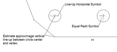
Next, we are going to sketch the two circles using the
circle tool ( ![]() ).
Start with the leftmost circle and try to line up the center of the circle with
the vertex shown in the following figure. Then, create the second circle to
the right of the first one. As you move your mouse to locate the center of the
next circle, you should see the symbol to assume that they are lined up horizontally.
).
Start with the leftmost circle and try to line up the center of the circle with
the vertex shown in the following figure. Then, create the second circle to
the right of the first one. As you move your mouse to locate the center of the
next circle, you should see the symbol to assume that they are lined up horizontally.
As you sketch the circle, look for the equal radii symbol to appear. The resulting sketch will look like the figure below.
Now, we are going to go back to the line tool, and sketch a line starting at the center of the rightmost circle, and going parallel to the side edge, as we can see in the following figure.

Be sure to see the parallel symbol appear when the line is parallel to the appropriate side. Since we don’t really need this line to create geometry, we are going to turn it into a construction line (similar to a centerline, but with a fixed length). To do this, we are first going to select on the line so it turns red.
Then, we will hold down the right mouse button over the line and select the Construction option, as shown in the next figure.

Once we do this, the line will become dashed, indicating that it is not a solid sketcher line anymore, but a construction line that is for reference only. The figure below shows this resulting construction line.

We are going to repeat this same process to create another construction line. This will be the line that runs down the center of our slot. Therefore, start by creating a solid line that originates at the top of our existing construction line, as shown below.
Be sure that no automatic constraint is applied (such as another parallel or perpendicular or equal length, etc.). Next, select this new line and right mouse click on it and select Construction, just as we did with the last line. It will become a construction line, as shown in the following figure.

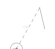
Now, we will sketch our slot. To start the slot, we know
that the top arc’s center lies on the intersection of the two construction
lines, therefore, we will use a center-ends arc ( ![]() ) and start by clicking on the vertex
where the two construction lines meet.
) and start by clicking on the vertex
where the two construction lines meet.
When you drag out the diameter/radius for the arc, try to get your starting location to be on an invisible line that is perpendicular to the second construction line, through the center of the arc that we are sketching, as shown below.

Once you click with the left mouse button to start the arc, move your mouse cursor to the opposite side of the construction line, thus forming an approximate 180 degree arc, as shown in the following figure.

Now, we will return to our line tool, and sketch a line at the right endpoint of this new arc. We want to make sure the line is tangent (look for a “T” symbol) to the arc, and parallel and equal in length to the short construction line, as shown on the next page.

To sketch the bottom arc, we will use a tangent-end/3-point
arc ( ![]() ).
Start by clicking on the end of the solid line that we just sketched. When the
green circle with the “X” appears, come out of the bottom quadrant, and move
the end of the arc over so it creates an approximate 180 degree arc, as shown
below (NOTE: the arc center should snap to the end of the construction line,
and our equal length symbols disappear).
).
Start by clicking on the end of the solid line that we just sketched. When the
green circle with the “X” appears, come out of the bottom quadrant, and move
the end of the arc over so it creates an approximate 180 degree arc, as shown
below (NOTE: the arc center should snap to the end of the construction line,
and our equal length symbols disappear).

When we click with the left mouse button to finish the arc, the green circle will go away, and our resulting arc will look like the following.

To finish the slot, we are going to use a line tool again, and connect the two open arc ends. A tangent symbol “T” should appear at both ends if we sketched the arcs at approximately 180 degrees.

Now that we have sketched the entities for our section, we are going to address any constraints that we have. Remember, the sketcher steps start with sketching, followed by adding/removing constraints.
We have a lot of “weak” constraints on the sketch already. To turn a weak constraint into a strong constraint, you first select the constraint so it highlights in red, the hold down the right mouse button and select Strong.
We will do this for all of our weak constraints, shown in the following figure.

Once you make these constraints strong, they will turn into a bold yellowish cream (black in this guide) instead of the gray color they once were, as shown on the next page.

There is only one constraint that we are missing. To add a constraint, we will click on the following icon in the sketcher toolbar.
![]()
When the constraint window appears, select on the icon used to line up two vertices on an invisible vertical line, as shown below.
![]()
We will then select the center of the right leftmost circle, and the vertex below it on the outside boundary, as shown below.

Once we do this, two bold rectangles will appear that face each other, indicating that these entities are lined up vertically.

Our sketch is now fully constrained the way we want it. Now, we must address the dimensions. Therefore, turn back on the view of dimensions. Your model should have a lot of gray (weak) dimensions on it.
The figure below shows the dimensions that are on my model but yours may be slightly different.

You should NEVER leave dimensions weak. Therefore we will either add new dimensions (which automatically come in strong), or convert weak dimensions over to strong dimensions that are already in the sketch that we want.
For example, there are many angular dimensions on this sketch that are the ones that we want, so instead of re-creating these dimensions, we can simply select them with the left mouse button, then hold down the middle mouse button and select Strong. In this example, we have the following dimensions that already exist that we will make strong. (NOTE: Your sketch may or may not have these exact dimensions, but don’t worry, you can always create the correct ones). Also, the figure below omits the rest of the dimensions for clarity; on your screen you will see all of the dimensions that are available.

Once the dimensions are made strong, they will appear in a bold yellowish cream color (black in this guide), and they stand out from the weak gray dimensions, as shown below.

Now, we are going to create the rest of the dimensions that we need. When we create a dimension, it comes in strong automatically, and one or more weak dimensions will disappear to leave the sketch fully constrained.
We will start by clicking on the dimension tool ( ![]() ). The first
dimensions that we will add will be the lengths of the lines around the border
of the sketch. To dimension the length of a line, simply click on the line
once with the left mouse button, and then place the dimension by clicking with
the middle mouse button where you want the dimension, as illustrated for our
first dimension below.
). The first
dimensions that we will add will be the lengths of the lines around the border
of the sketch. To dimension the length of a line, simply click on the line
once with the left mouse button, and then place the dimension by clicking with
the middle mouse button where you want the dimension, as illustrated for our
first dimension below.

We will repeat this process to create all of the rest of the seven linear dimensions around the outside of the sketch, as shown below.

Notice that many of our weak dimensions are gone. Now, we will repeat this same sort of process to dimension the distance between the slot and the left hole, and the length of the slot itself.
We will click once with the left mouse button on the construction line between the left hole and the top of the slot, and then use the middle mouse button to place the dimension. Do the same for the other construction line that goes between the two arcs in the slot. The resulting dimensions look like the following.

The next dimension will be the width of the slot itself. To create this dimension, click on the right outside straight edge of the slot with the left mouse button, then click on the left outside straight edge of the slot with the left mouse button, and then use the middle mouse button to place the dimension, as shown below. Again, the surrounding dimensions have been omitted from the following figure for clarity only.

Our next dimension is the distance between the two holes. To create this dimension, select on one of the circle centers with the left mouse button, followed by the other circle center (using the left mouse button again), and then click with the middle mouse button to locate the dimension.

There is only one more dimension on this sketch that needs to be created. It is an angular dimension on the right side of the sketch. To create an angular dimension, select on one of the angular lines with the left mouse button, followed by the other angular line (also using the left mouse button). Once both lines are selected, place the dimension using the middle mouse button. The following figure shows this angular dimension.

All of the weak dimensions should be gone. If not, you either do not have all of the dimensions placed on the sketch, all of them have not been made strong yet, or you do not have enough constraints, as defined earlier.
The fully dimensioned sketch should look like the figure at the top of the next page.

Once we have all of the dimensions created and strong, it is time to modify them. Notice that most of our linear dimensions are on the order of a few inches (largest is about 4.3 inches). However, in our exercise, the smallest linear dimension is actually 19 (the width of the slot).
If we were to simply try to modify each dimension one-by-one, our sketch would either fail regeneration, or it would terribly distort. The best approach in this case is to use the lock scale option to scale up the sketch to a better range of dimensions.
To do this, we will first click on the following icon in the sketcher toolbar.
![]()
We will drag a box around the entire sketch. All of the dimensions, constraint symbols and sketched entities (lines, arcs, circles, etc.) will turn red.
Next, we will click on the modify icon ( ![]() ). This will bring up the
window shown at the top of the next page.
). This will bring up the
window shown at the top of the next page.

To lock the scale, we will first click in the box to the left of the words “Lock Scale”. Next, we select on the dimension that we want to change that will drive all other dimensions to update. In this case, we will scroll through the available dimension fields until we see the one that represents the linear dimension on the horizontal line (the one marked “H”).
When we select on this dimension from this window, a box will appear around the dimension on the sketch, as shown in the following figure.

We will then edit the value for this dimension to 94.0. Once we hit the enter key, all of the dimensions in this modify window will change to match the same scale as the dimension value that we entered, as we can see in the following figure.

Now, we can click on the green check mark, and the entire sketch will re-appear in the window. Notice that all of the dimensions are closer in value to the correct values in the exercise. This is shown at the top of the next page.

We can now modify each of the dimensions separately by double-clicking on them and entering a new value. Because the dimensions are closer to the correct value, the sketch shouldn’t warp as bad as it would had we tried to go from 1.5 to 81 (for example).
Once all of the dimensions are modified, our sketch looks like the picture on the exercise page, as shown below.

Save the sketch, then use Window, Close to finish.
Sketch 2 – Latch Plate
When we look at this sketch, we can see that it is symmetric about a horizontal centerline. Therefore, our goal is to take advantage of this symmetry by sketching only half of the shape, and then mirror it.
Therefore, we will start by creating a new sketch, called Latch_Plate. The first entity will be a centerline. To create this, click on the following icon in the line tool flyout.
![]()
Click out in the middle of the sketch window, and snap the centerline so it is horizontal (you should see the “H” symbol), as shown below.

Now, we are going to use the line tool to sketch the following shape (and it probably works best and fastest in the order shown below).

In the figure above, “LMB” means “Left Mouse Button” and “MMB” means “Middle Mouse Button”. Be sure to avoid any equal length constraints or any “line up horizontal or vertical” constraints. You should only see horizontal “H” and vertical “V” constraints, and two collinear constraints where the lines connect to the centerline.
Also, there is no line connecting the two points that lie on the centerline, it is left open for now.
The next thing we will do is create a fillet at the upper left corner of the sketch. To do this, click on the following icon.
![]()
Then select the two lines that intersect in the upper left corner of the sketch, as shown in the figure at the top of the next page.

The resulting fillet will look like the following.

Repeat this process to create the other fillet near the right side of the sketch, as shown completed below.

The next thing we will sketch will be the circle that lies at the center of the first fillet that we created. Therefore, click on the circle tool, and then click with the left mouse button on the fillet arc center and drag out the radius. Click with the left mouse button to finish the circle, which will look like the figure at the top of the next page.

Next, create another circle. When selecting the location for the center of the circle, try to get the “Line up Horizontal” symbol to appear first, and then click on the sketch approximately below the vertex shown in the following figure. Drag out the radius until you see the “Equal Radii” symbol appear.

We have two arcs left to create. Therefore, click on the center-ends
( ![]() ) arc tool,
and create a 90-degree arc at the location shown in the following figure.
) arc tool,
and create a 90-degree arc at the location shown in the following figure.

Be sure to make the arc large enough so that no equal radii symbols appear on it. If you get an equal radii symbol, you can delete it later.
Now, we are going to use a tangent-end/3-point arc ( ![]() ) and click at the
end of the arc that we just made, and drag out the end of the arc to other line
end, as shown below.
) and click at the
end of the arc that we just made, and drag out the end of the arc to other line
end, as shown below.

The following figure shows our half section after we are done sketching all of the entities.

Normally, we would finish sketching the entire section before addressing the constraints, but in the case of mirroring, it is best to get your section and constraints in order before you mirror, but we will not deal with dimensions at this time.
Therefore, we will first start by turning all of our weak constraints into strong ones. The figure at the top of the next page shows all of our constraints once we turn them to strong constraints.
NOTE: If you do not have one or more of these constraints, you can always add them at this time.

We need to add one additional constraint before we mirror.
We will use the ![]() icon,
followed by
icon,
followed by ![]() and
select the center of the right circle with the vertex at the top of the model
that is lined up with this circle. The result is shown below.
and
select the center of the right circle with the vertex at the top of the model
that is lined up with this circle. The result is shown below.

To mirror the sketch, we will first use the select tool ( ![]() ) to drag a box
around the entire sketch so that all the entities, and constraints become
selected. Next, we will click on the mirror tool, which looks like the
following icon.
) to drag a box
around the entire sketch so that all the entities, and constraints become
selected. Next, we will click on the mirror tool, which looks like the
following icon.
![]()
Select on the horizontal centerline that we sketched, and our section should now be one complete sketch, as shown at the top of the next page.

You will see a bunch of arrows. These arrows represent a “symmetric” constraint, and are always set on vertices or arc centers when you mirror a sketch.
We will need to add one additional constraint before we are
ready to dimension. To do this, we are going to go back into the constraint
tool, then select the collinear constraint ( ![]() ). We are going to select on the two
arc centers shown in the following figure.
). We are going to select on the two
arc centers shown in the following figure.

When we do this, they will snap on top of each other (align). The result will look like the following.

Our sketch should now look like the following.

Now, we are going to turn off the display of constraints by clicking on the following icon.
![]()
Then, turn on the display of dimensions (use the ![]() icon to do this).
Our weak dimensions appear on the sketch, as shown below.
icon to do this).
Our weak dimensions appear on the sketch, as shown below.

NOTE: I have moved the weak dimensions around to see them more clearly.
As we did in the last exercise, we will look for any dimensions that we need that are already in the sketch, and turn them into strong dimensions. We do this by selecting all of them using the Ctrl key, and then hold down the right mouse button and select Strong.
The following figure shows the resulting dimensions in this example that are already there and have been converted to strong.

Now it is just a matter of adding additional dimensions until we get the dimensioning scheme that we saw in the exercise. The resulting dimensioning scheme is shown below.

The last thing we must do is modify the dimensions to their correct values. Unlike the last exercise, we don’t have a huge jump, but we want to be careful in the order that we pick if we just want to modify one-by-one.
The other option is to select all of the dimensions by dragging a box around the entire sketch, select the modify tool, uncheck the Regenerate option, and then modify all of the dimensions one-by-one in the modify window.
When we are done, we click on the green check mark, and our sketch will regenerate and look like the final version that we need, as shown below.

Save this sketch, and click on Window, Close to finish out of the section.
LESSON 5 – Sketch Feature
Start by going to File, New from the menu bar, and when the window opens, make sure that Part is selected, and enter Plate_Layout, for the name, as shown in the next figure.

The Sub-Type should be Solid. Click on OK and you will get the next window.

For this model, our units are in inches, so select the startpart_english file, or whatever equivalent English start part you may have. Click on OK to continue. You will see your default datum planes (assuming they are turned on).

From the datum fly-out icon, select on the Sketch tool, or use Insert, Model Datum, Sketch, from the menu bar. We will get the following window.

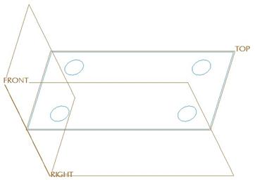
We will pick on the TOP datum plane to use as our sketching plane. When we do this, it automatically assumes we want to use the RIGHT datum plane as a reference, and faces it towards the Right, as shown in the next figure.

There is a yellow arrow pointing down from the TOP datum plane, indicating the viewing direction. We will accept this, and click on the Sketch button. This places us into our 2D sketch mode. Turn off datum planes, and you will see the following.

We can see two orange dashed lines. These lines are NOT centerlines. They represent sketcher references. Our sketcher references window should be open, and we can see that the FRONT and RIGHT datum planes (which are perpendicular to the TOP datum plane – our sketching plane) have been selected automatically as sketcher references.
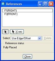
We will not need to select any additional references at this time, so we will click on the Close button. We will now use a rectangle tool and sketch a rectangle where the lower left corner lays at the intersection of the two sketcher reference lines.
When the rectangle is done, we will go ahead and modify the dimensions to 10.000 and 5.000. NOTE: The reasons we are going ahead and modifying the dimensions at this time are two-fold:
· The sketch is simple enough that modifying the dimensions now will not cause the sketch to fail.
· The dimensions originally come in very large compared to our final values. Modifying the two dimensions now will cause the sketch to scale down so our remaining entities will be closer to their final values.
The sketch should look like the following at this time.

We will now switch to the circle tool. Sketch a circle in the upper left corner of the rectangle. Change the dimension values to their correct values as shown in the next figure.

Next, we will sketch a second circle in the upper right corner of the rectangle. When placing the circle, snap to a horizontal alignment, and also snap to equal radii. Modify the single dimension to its correct value, as shown in the next figure.

Now, we will sketch the circle in the lower left corner. Be sure to align vertically with the first circle, and snap to equal radii. Modify the single dimension that appears, as shown in the following figure.

The last circle should be easy. It will snap at the horizontal alignment to the third circle, and vertically to the second circle. The equal radii value will also snap. No dimensions will be necessary for this circle. The final sketch looks like the following.

Click on the blue check mark to complete the sketch, turn on your datum planes, and go to a default orientation. Your model will look like the following.

Save and close this model.
LESSON 6 – Extrude Feature
Plate_Layout
Open up the Plate_Layout2 model. It consists of two sketched features, as we can see in the model tree.

The model looks like the following.
We will start by selecting on the Sketch_Plate sketch from the model tree so it highlights in red on the model. Now, pick on the Extrude feature. When we do this, the dynamic preview automatically appears, because we have decided to use an external sketch.

We will change the depth to 2.0 inches, and then click on the green check mark to complete this first extrude feature. Our model looks like the following (no hidden mode).

In our model tree, we can see that the first sketch is now hidden, because it has been used in an extrude feature.

If we need to see this or use this sketch again, we can always unhide it. For now, we will pick on the second sketch (SKETCH_CIRCLES), and then click on the extrude icon again.
This time, when our dashboard opens, be sure to select on the Remove Material icon. Change the depth value to 1.0, and be sure it is going up into the part, as shown in the next figure.

Click on the green check mark to complete this extruded cut, and then rotate the model to see the result.

Save and close this part.
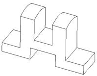
Safety_Key
Create a brand new part called Safety_Key. Use an English start part (if available). While there may be multiple ways to create this part, we will demonstrate one method that utilizes simple sketches, and a low number of features. We will also use internal sketches. To do this, first select the extrude tool, and then right click on the working window and select Define Internal Sketch.
The following images show the progression of this model.
Extrude 1 – TOP plane as Sketching Plane, RIGHT plane facing towards the Right.

SKETCH


DYNAMIC PREVIEW FINISHED EXTRUDE
Extrude 2 – Select Use Previous for sketching plane and sketching reference.

SKETCH


DYNAMIC PREVIEW FINISHED EXTRUDE
Extrude 3 (Cut) – FRONT plane for sketching plane, RIGHT plane facing towards the Right.

SKETCH

OPTIONS SLIDE-UP PANEL


DYNAMIC PREVIEW FINISHED EXTRUDE
Extrude 4 (Cut) – RIGHT plane as sketching plane (default viewing direction), TOP plane facing towards the Top.

SKETCH


DYNAMIC PREVIEW FINISHED EXTRUDE
NOTE: For the dynamic preview, you will need to change the depth option to Through All, and flip the direction to go back into the part, as shown in the figure above.
Save and close this model.
IMPORTANT: For the first cut feature, we chose to combine the circular hole and the rectangular cut-out in a single extrude feature. For greater flexibility, you may wish to separate them, but for this example, both are very simple shapes, and easy to modify in the same sketch. If you were required to delete one of these entities, you would have to edit the sketch and remove the profile.
Rod_Support
Create a brand new part called Rod_Support. Use a metric start part (if available). As with the last part, we will demonstrate the preferred method for creating this part using simple sketches and flexible features.
Extrude 1 – RIGHT plane for Sketching Plane, and TOP plane facing towards the Top.

SKETCH


DYNAMIC PREVIEW FINISHED EXTRUDE
Extrude 2 (Cut) – FRONT plane for Sketching Plane, RIGHT plane facing towards the Right.

SKETCH

OPTIONS SLIDE-UP PANEL

DYNAMIC PREVIEW FINISHED EXTRUDE
Extrude 3 (Cut) – TOP plane for Sketching Plane, RIGHT plane facing towards the Right.

SKETCH


DYNAMIC PREVIEW FINISHED EXTRUDE
NOTE: A Through All depth is used for this cut, and the direction must be flipped to go through the part.
Extrude 4 (Cut) – RIGHT plane for Sketching Plane, TOP plane facing towards the Top.

SKETCH


DYNAMIC PREVIEW FINISHED EXTRUDE
Again, the dynamic preview indicates a Through All cut that goes back into the part, resulting in the finished part shown above on the right. We could have created this hole in our first extrude feature as well. The same rules apply, if we needed to separate out the features later, we would have to redo the sketches for the features.
Save and close this model.
LESSON 7 – Making Changes
Open up the Plate_Layout2 model that we created in Lesson 6. Right now, we have a 10” x 5” x 2” plate that has four 1” holes going 1” into the part.
To turn these holes into feet sticking out of the model, we must change a protrusion into a cut, and we must change both the direction and depth of the feature. To do all of this, we will need to use the Edit Definition command.
Therefore, we will select on the Extrude 2 feature from the model tree with the right mouse button, and select Edit Definition, as shown in the next figure.

This brings us back into the dashboard for the feature, and it looks like the dynamic preview we saw before:

The first thing we will do is to de-select the Remove Material icon, turning the extrude from a Cut into a Protrusion. The preview now shows solid shading for these holes, as shown in the next figure.

Next, we will click on the yellow arrow to flip the direction of the feature, and change the value to 0.5. The preview now looks like the following.

Click on the green check mark to complete the changes to this feature, and now our model looks like the following:

Save and close this model.
LESSON 8 – Datums Part 1
Create a new part called Angle_Bearing. The trick to this exercise model is to understand that our raised cylindrical protrusion, and the hole that goes down it are perfect circular shapes when viewed at the section A angle.
Therefore, we need to have a sketching plane that is parallel to this section plane. So, the trick is getting that sketching plane. Once you have that, everything else is relatively simple.
Extrude 1 – “T” shaped base
We will start by creating an extrude feature. Use an internal sketch, and use the FRONT datum plane as the sketching plane. Face the RIGHT datum plane towards the Right, and sketch the following profile.

Click on the blue check mark to complete the sketch, and use a symmetric depth of 103.0, as shown in the dynamic preview.

Click on the green check mark to complete this first extrude feature. The model currently looks like the following.

Now, we will start to create our datum features.
Datum 1 – Datum Axis
To get started, we need to create a datum axis. Why? In order to have a datum plane that is at an angle (as our section “A” plane is), we need an edge or axis to revolve through. We can’t simply use an edge on the model, because we need to control where the axis of the cylinder connects with the right edge of the model (as indicated by the 33.0” dimension).
Therefore, we will click on the datum axis tool (or use Insert, Model Datum, Axis from the menu bar). This brings up the following window.

We will create an axis that is normal to a surface, located from two additional surfaces. Therefore, select on the following surface location.

When we do this, the surface highlights in a mesh (in no hidden mode – or a rose-color shade in shaded mode). We can also see two drag handles to locate the axis, as shown in the next figure.

We will drag one of the handles over to the front “T-shaped” face, and the other to the side rectangular surface, giving us two linear dimensions, as shown in the next figure.

Your dimensions will be different unless you picked the exact location I picked in this example. We will modify the distance to the front face to 33.0, and the distance to the side as 0.0, as we can see in the following figure.

This places the axis exactly where we need it for our first datum plane. At this time, our axis window looks like the following.

We will click on OK to finish this axis, and turn on the display of datum axes to see the result.