|

Lesson Objective: In this lesson, we will learn about the Gear Pair entity.
USAGE OF GEAR PAIRS
Gear pairs are used to simulate two gears in your mechanism. Many times, you may wish to avoid having to model gears and figure out (either using Cams, or some other method) a way to get them to work properly. This mechanism entity will not only provide you with a way to simulate the gears working together, but can calculate forces and loads as well.
There are two different types of gear pairs that can be created:
· Standard – Use this when you want your two gears to rotate in the same or opposite directions, such as a spur-spur or worm and wheel gear.
· Rack and Pinion – Use this when you want to be able to translate rotational motion into translational motion.
EXAMPLE 1 – STANDARD GEAR PAIR
In this first example, we are going to create a system of planetary gears, like you might find in an electric screwdriver. Therefore, open up the model entitled Planetary_Gear.asm, which initially looks like the following.
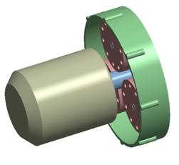
This assembly consists of two sub-assemblies. The first sub-assembly is the motor assembly, which consists of the motor base, and the motor shaft (which also represents our small gear).
The second sub-assembly represents the planetary gear which consists of a fixed plate, three medium gears, and one large gear, which represents our chuck.
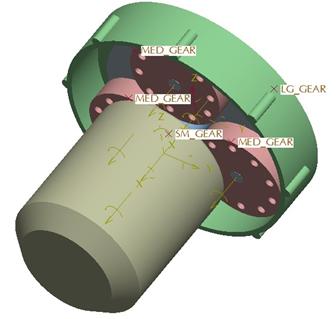
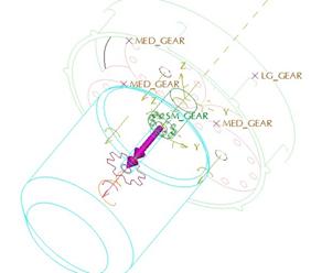
The following figure shows the five different gear representations in our model. Please note which medium gear number identifies which gear, as we will refer back to this when defining our gear pairs.

I intentionally put holes in the small and medium gears so we can see the actual motion of them once we are done. Other than the holes, we did not have to worry about modeling gear teeth. We could have modeled gear teeth, but they would not have contributed to the final mechanism we create.
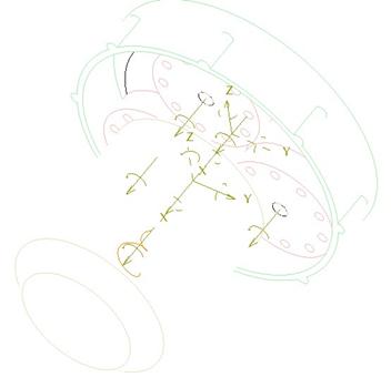
We will now go to Applications, Mechanism to look at the current connections. The motor sub-assembly has a pin connection for the shaft which allows the small gear to rotate. The planetary gear sub-assembly contains four pin connections that allow the three medium and one large gears to spin.
These sub-assemblies were placed together using two general connections to offset the plate from the motor. These general connections do not prevent the pin connections from working, unlike a rigid connection. The following figure shows the different pin connections.

Finally, the last thing to point out on this assembly are some datum points that are built into the gear models. When we define gear pairs, we need to have a datum point or vertex that we can use to graphically show the outline of the gear. We place this datum point right on the circumference of our gear model to define the diameter. The following figure shows the different datum points.
Servo Motor Definition
Before we define our gear pairs, we will define a servo motor that will drive the motor rotation. Therefore, create a new servo motor called Motor_Turn, and use the pin connection for the small gear. For the profile, we will use Velocity at a constant value of 600 deg/sec, which equates to 100 rpm.
The servo motor window will look like the following.

The following figure shows the servo motor on the model once it is complete.
Circular Pitch
One more thing to discuss before we create our gear pairs. If you recall from gear 101, a gear ratio can be defined as the diameter of one gear to another. It is often defined by the number of teeth of one gear to another, but since we don’t have actual teeth on our model, we use the Circular Pitch (or in Pro/E referred to as the Pitch Circle).
The following are the pitch circles for the different gears:
· Small Gear = 0.3
· Medium Gear = 0.9
· Large Gear = 2.1
Therefore, our large gear should be reduced down from the small gear by 7 (2.1/0.3). If the velocity of the small gear is 600 deg/sec, then our resulting velocity for our large gear ought to be 600/7 = 85.7143 deg/sec. We will take measures at the end to confirm this.
We are now ready to define our gear pairs. Just like cams, we have to have a gear pair for every two gears that come into contact. Therefore we will need 6 gear pair definitions. One for each of the interactions between the small gear and the three medium gears (3), and one for each of the interactions between the medium gears and the large gear (3).
Gear Pair 1 – Medium Gear 1 to Small Gear
To create a gear pair, click on the following icon in the feature toolbar.
![]()
This brings up the familiar “create entity” window. Click on New to create a new gear pair. This brings up the following window.

The first thing we are going to do is enter a new name for this gear pair, called Sm_Med_1 to signify that it is between the small gear and the medium gear 1 listed in one of the previous figures.
For the type of gear, we will leave the Standard value alone. Next, we are defining Gear 1, indicated by the Gear1 tab. For the joint axis, we will pick on the pin connection for the small gear (see previous figure). When we do this, it should automatically determine which body is the gear versus the carrier. The Carrier is typically the body that remains stationary. Since a pin connection is made from two bodies (the motor and the shaft), the motor is selected as the carrier, and the shaft is selected as the gear.
If we had two bodies that moved (such as two links in a bar linkage), we could flip which body is the gear and which is the carrier.
Once we select the pin connection, we should see the following on the model.
We can see the gear symbol and two magenta arrows. In our window, we will type in 0.3 for the Pitch Circle, and then select the SM_GEAR datum point to determine the Icon Location. Once we do this, the gear symbol moves to the plane where the datum point is located, as shown in the next figure.

The data for Gear1 looks like the following at this point.

Now, click on the Gear2 tab, and select the pin connection for the Medium Gear # 1, as defined in a previous figure in this lesson. Once we select this, enter 0.9 for the Pitch Circle, and pick on the MED_GEAR datum point for this gear to location the icon.
The model will now look like the following.

Our Gear2 window looks like the following.

When we click on the Properties tab, we see the following.
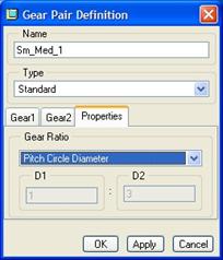
We can see that our current definition for the gear ratio is determined by using the pitch circle diameters. The other option is to create a user-defined pitch, in case we didn’t model our circles at the correct diameters.
We will leave it at the current value, and we can see that the ratio of D1 (small gear) to D2 (medium gear) is 1:3.
On the model, the outline of the gear pair adjusts to the correct diameters, and we can see straight lines on each gear symbol, indicating the location of the joint axis zero location for each gear, as seen in the next figure.

Click on OK to complete this first gear pair definition, and our model will now show a connecting line between the two gear pairs, as we can see in the next figure.

Sm_Med_2 and Sm_Med_3 Gear Pair Definitions
The easiest way to create the next two gear pairs between the small gear and the remaining two medium gears is to copy the first gear, and then select a different pin connection and datum point for Gear2 for each. We will not need to redefine Gear1 because it is the same for the other two.
Just make sure that you rename the gears to Sm_Med_2 and Sm_Med_3, and pick the appropriate pin connection and datum point based on the figure early in this lesson.
Once all three gear pairs are defined, you should see the following on your model.

Lg_Med_1, Lg_Med_2 and Lg_Med_3 Gear Pair Definitions
To create the three gear pairs that go between the large gear and the three medium gears, copy the existing three small gear/medium gear pairs. For each copy, rename it to the appropriate LG_ name, and then redefine Gear1 to select the pin connection and datum point that correspond to the large gear. Don’t forget to enter a pitch circle value of 2.1.
Once all six of the gear pairs have been completed for the assembly, it will look like the following.

Save your assembly, and we are now ready to create our analysis.
Analysis
Create a new kinematic analysis, called Spinning_Gears. Keep the timing options the default values, and make sure that the servo motor is running from start to end. Run the animation, and you should see all of the gears spinning.
To see a captured movie of these gears spinning, open up the Planetary_Gear.mpg movie in your training directory.
Measures
The last thing we are going to do for this assembly is confirm that our gears are working properly. The easiest way to do this, is to check the velocity for the large gear. To do this, click on the create measures tool, and create a new measure called LG_Gear_Velocity. Set the type to Velocity, and pick on the pin connection for the large gear. Keep the default of Each Time Step selected.
Back in the measures window, we should see a value of 85.7143, as we can see in the next figure.

This is exactly 600/7, which we said it should be, therefore, our gear pairs are doing exactly what they should be doing.
EXAMPLE 2 – RACK AND PINION GEAR
We’ve all heard of rack and pinion steering, where a rotational turn of the steering wheel causes a linear translation of a rod connecting the wheels (simplified). This is what a rack and pinion type of gear pair is doing, and we will define one now.
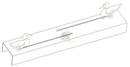
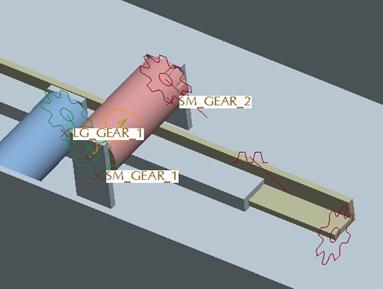
To demonstrate this, open up a model called Sitting_Duck, which will simulate an arcade-style duck hunting game. It looks like the following.

We have two duck models sitting on sliding rails that have gear teeth at the bottom (not modeled). The two rails are touching two gears, one of which is driven by a servo motor to move the ducks across the field in 5 seconds, and the other has a standard gear set up between them.
If you go to mechanism mode, you can see this initial setup, as shown in the next figure.
For consistency, we will use the following convention.

We are going to be creating two rack and pinion gear pairs between Rail 1 and the small gear, and between Rail 2 and the large gear.
Sm_Rack_Gear
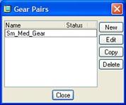
We are going to click on the gear pair icon. When we do, we will see the current gear pair that is defined, as shown in the next figure.
Click on New, and when the window opens, enter Sm_Rack_Gear for the name, and change the type from Standard to Rack and Pinion, as shown in the next figure.

This changes the tabs to say Pinion and Rack instead of Gear1 and Gear2, respectively. The Pinion tab is used to define the rotational gear. We will click on the black arrow under the Joint Axis section, and pick on the pin connection that sits on the small gear. Enter 1.0 for the Pitch Circle Diameter, and then pick on the SM_GEAR_2 datum point for the Icon Location.
The model should look like the following.

Now, we will click on the Rack tab, and for the joint axis, pick on the straight arrow on the slider connection for Rack 1. When asked to pick the Pitch Line, we will pick on the following vertex.

Click on OK to finish this gear pair, and you will see the following in your model.
Lg_Rack_Gear
Create a second gear pair using the Rack and Pinion option, and this time for the Pinion, pick the pin connection on the large gear model, and use a diameter value of 1.0. For the datum point, pick on the LG_GEAR_2 point.
For the Rack, pick on the slider connection on the Rail 2 model, and pick on the equivalent vertex for the pitch line, as shown in the next figure.

One of the last things we are going to do for this definition, is to flip the positive direction of the rack using the button shown below.
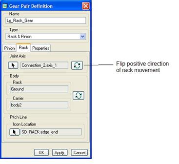
This will make the magenta arrow for this rack body look like the following.

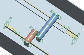
Now, click on OK to complete this gear pair, and our model will look like the following.
Before we run the analysis, go to your drag tool, and take a snapshot of the assembly with the ducks at the end positions. Call this snapshot Start. We will now go into our analysis.
Analysis
Open up the analysis tool, and edit the existing analysis (Duck_Move). Change the starting position to use the Start snapshot, and then run the analysis. If everything is defined correctly, the ducks will move towards each other and stop in the middle.
To see a captured animation, open up the Sitting_Duck.mpg movie file in your training directory.
Save and close this assembly.
LESSON SUMMARY
Gear pairs are very powerful, and very useful for representing different types of gears without having to worry about modeling gear teeth and trying to create cams to get the gears to connect.
Be careful to check the positive direction of rotation and translation for your different gear bodies.
EXERCISE
Open up the model entitled Hand_Mixer.asm, which looks like the following.

The goal for this exercise is to be able to animate the crank wheel going around and see the mixer blades spin in the correct direction. In this case, you have bevel gears, but the Standard gear pair should work nicely.
To see a completed movie of this hand mixer in action, open up the Hand_Mixer.mpg movie file in your training directory.
Save and close this assembly when finished.