Lesson 220

Lesson Objective: In this lesson, we will learn about the General connection and redundancies in the mechanism model.

USAGE OF GENERAL CONNECTIONS
A general connection is one in which no specific degree of freedom is explicitly set. You will be able to fix degrees of freedom one-by-one with this connection by using regular placement constraints, such as Align, Mate, etc.
Once you have defined some constraints, Degrees of Freedom will start to be eliminated. Any open DOF will still be available for the mechanism. The resulting DOF will be shown on the symbol for the connection.
REDUNDANCIES
Before going any further with the general connection, it is a good time to talk about redundancies in the model. What are redundancies? Any time you add two or more connections to a model that provide for the correct motion of an assembly but do not further constrain the model, you have redundancies. A great example is a door assembled using two pin connections for each hinge.
Once you add the first pin connection, you have fixed the door to having only one rotational degree of freedom. Adding a second pin connection will not prevent the door from swinging properly, but it does not restrict any additional movement at all, and therefore is not necessary.
Why do we care? Unfortunately, redundancies in the model can lead to incorrect calculations of load reactions and forces in a dynamic analysis. The goal then, should be to evaluate other potential combinations of connections that will give the same overall DOF restrictions, but not cause redundancies in the model.
So, with the door example, an alternative might be to use a planar connection that restricts 3 DOF (1 translational and 2 rotational) and a bearing that restricts 2 DOF (2 translational). This leaves one rotational DOF, which is what a pin connection gives us.
EXAMPLE - ROBOT
Open up your Robot.asm assembly that we worked with a while back. Use Mechanism, Connect to return it to its starting position, and then delete all of the servo motors and the analysis. Create a new servo motor on the pin joint that connects Robot3 to Robot 2, and use a Ramp with the following values: A = 0, B = 6. This will move Robot 3 60 degrees in 10 seconds.
Once you have this defined, create a new kinematic analysis where this motor runs from Start to End, and run the analysis to make sure that the arm is moving up 60 degrees during the analysis. If it is, we are ready to add our general connection to Robot 4. Use Mechanism, Connect to go back to the starting position.
Return to Application, Standard to get back to regular assembly mode. We will start by editing the definition of Robot4. When we do this, we see the following.
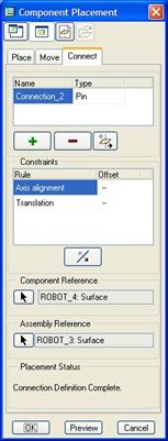
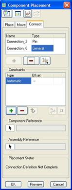
We can see the current pin connection. We will click on the green “+” button to add another connection. Change the type to General, and we will see the following.
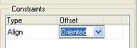
Before we pick any references, we are going to explicitly define an Align and Oriented condition, as shown in the next figure.
Then, select the top flat surface of Robot2 and the top flat surface of Robot4, as shown in the next figure.
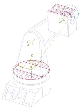
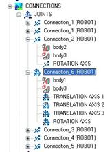
When we do this, we will be removing two rotational degrees of freedom from this robot component. If we look at our model tree and expand the connections, and drill down into our general connection, we can see that we still have three translational and one rotational degree of freedom open on this connection.
Return to Mechanism mode, and re-run the analysis. This time, the robot 4 component does not rotate up, instead it remains parallel to the ground.
Close this assembly without saving.
LESSON SUMMARY
A general connection is used to allow for traditional placement constraints, while still allowing for motion of the component (unlike the rigid connection), but does not have a completely open DOF state, like the 6DOF connection.
Remember to watch out for redundancies when you run a dynamic analysis. Use the DOF measure to check how many degrees of freedom are still open and use the redundancies measure to determine if you have redundancies in your assembly connections.
EXERCISE
None