Lesson 190

Lesson Objective: In this lesson, we will learn how to create a damper in Mechanism.

USAGE OF DAMPERS
A Damper is used to dampen the energy of a mechanism. For example, an air cylinder on door hinge is a great example of a damper, as it forces the door to close at a controlled rate, rather than just slamming shut.
In Mechanism, a damper is created similarly to the spring entity, and like springs, will not appear on your BOM outside of Mechanism mode.
DEFINING DAMPERS
There are three methods you can use to define dampers. These are:
· Joint Axis – The damper definition is associated with a created connection, such as a slider or cylinder.
· Point-to-Point – The damper is created between two specified points or vertices in the model.
· Slot – The damper is created on a slot-follower connection. The body that contains the point is acted upon by the damping force from the curve. The force remains tangent to the curve at all points, and opposite the direction the body with the point is moving.
When you define a damper, you use the following equation:
F = C * V
Where F is the damping force, V is the velocity of the body in motion, and C is a damping coefficient. C can not be a negative value, and generally comes from manufacturer’s specifications or from empirical data.
EXAMPLE – CAM FOLLOWER
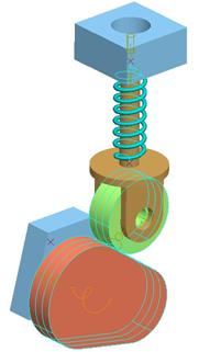
Open up the Spring_Example assembly that we worked on in the last lesson, and go to Mechanism mode. It looks like the following.
To create a damper, click on the following icon in the feature toolbar.
![]()
The familiar create entity window appears, and we will click on New. This will bring up the following window.
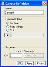
We will select the Point-to-Point option and then pick the same two datum points that the spring goes through (BASE_PNT and FOLLOW_PNT). For our “C” value, use 100. Our window will look like the following.
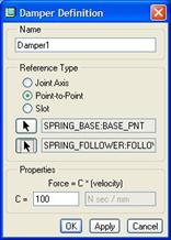
Click on OK to complete this damper definition, and you will see it on the model, as shown in the next figure.

It may be difficult to see the symbol embedded in the spring, so I’ll show you what it looks like in the next figure.
![]()
Close out of the damper window. We will now run our analysis again to view the results. From an animation standpoint, we don’t see anything different. The reason for this is because the servo motor spinning the cam is running at a constant velocity, and the amount of distance the piston is moving has not changed.
Where we would see a difference is in any calculated forces for the assembly during the analysis. We will see how to calculate forces in a later lesson. This exercise was mostly to demonstrate how to create the damper.
LESSON SUMMARY
Use dampers to simulate real dampening mechanisms in your assemblies. Create them on joint axes, between two points/vertices, or on slot followers.
EXERCISE
None