Lesson 130

Lesson Objective: In this lesson, we will learn about the bearing connection.
USAGE OF BEARING CONNECTIONS
A bearing connection is kind of a mix between a ball joint and a slider. It has 1 translational degree of freedom, and 3 rotational degrees of freedom. Do not confuse this with a typical ball bearing assembly, although each individual ball in that assembly might behave in this way.
There are very few real-world examples that come to mind when you think of this connection type. In most cases where a ball joint may be used, there are other components and connections that can provide for translational degrees of freedom.
You could use bearing connections to simulate in one object what multiple objects might accomplish when combined together.
Because of this, we will demonstrate how to set up a bearing connection with two components in an assembly that do not represent an actual object.
EXAMPLE – HOW TO
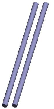
Open up the assembly entitled Bearing_Connection.asm. It consists of a single component, shown below.
Assemble in the Bearing_Slide.prt component. Be sure to turn on the display of datum axes and datum points. In the placement window, click on Connect, and then select a Bearing connection type. The placement window looks like the following.
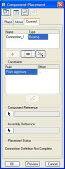
This window is a little misleading. The only thing is says for references is “Point Alignment”. This looks like you would align a datum point or vertex to another datum point or vertex. In actuality, you align a datum point or vertex to a datum axis, curve or edge.
In this case, we will pick on the BEARING_POINT datum point and the BEARING_AXIS axis, as shown in the following figure.
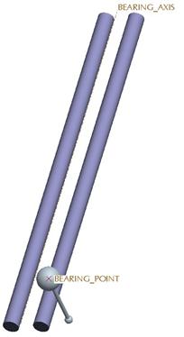
When we do this, the point snaps over to the axis. Click on OK to complete this assembly, and then go to Applications, Mechanism. We can see the symbol for a bearing connection looks like the one for a cylinder, except it only has a single straight arrow.
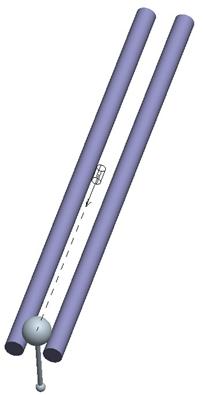
Click on the Drag tool and pick on the small sphere at the end of the Bearing_Slide component. You will see that as you drag the component, the large sphere stays on the track (follows the axis), but the end is free to rotate in all directions, centered on the datum point.
Close this assembly when you are done dragging.
SERVO MOTORS WITH BEARINGS
Unlike the Ball connection, you can create a servo motor for the translational component of the Bearing connection.
Again, the ability to control any rotation for this component would have to be done by connecting it up to another component that provides this motion. If you remember from the Planar exercise, we have the ability to set up motors on a variety of components to control motion, but we want to limit the number of motors to components that will directly carry out our motion.
In the case of a Bearing or Ball, you will have to rely on other components to provide rotational motion.
LESSON SUMMARY
A Bearing connection has four degrees of freedom – 1 translational and 3 rotational. You can control the translational joint axis settings and create servo motors for this translation. Rotational degrees of freedom can not be controlled directly.
EXERCISE
There are no exercises for this lesson.