|

Lesson Objective: In this lesson, we will learn about the Planar connection type.
USAGE OF PLANAR CONNECTIONS
A Planar connection is used to ensure that a datum plane or planar surface always touches another plane or planar surface. The object is then free to move in two translational directions within that plane, and it is able to rotate around the free axis that is normal to the plane.
You would use a planar connection to capture motion for:
· A computer mouse moving on a mouse pad
· A box sliding across a floor
· Any object that rests on a flat surface, but can be moved about that surface.
Generally, the planar connection is used in conjunction with other connections that ultimately fix some of the other open degrees of freedom.
EXAMPLE - DRAWER
Typically, when simulating a drawer that is able to open and close in a single direction, a Slider connection is best, but we will demonstrate how you can set this up with two planar connections. In an exercise, you will create an assembly motion that requires a planar connection.
To see this drawer example, open up the assembly called Drawer_Pln.asm, which initially looks like the following.

We are going to start by assembling in the Drawer_Pln.prt part file. Make sure your datum planes are visible. In the placement window, click on the Connect tab, and change the connection type to Planar. The window will look like the following.

We only have to pick two planes or planar surfaces. Therefore, we will pick the RIGHT datum plane on both models. When we do this, the drawer snaps over and lines up horizontally with the drawer body.
Use Ctrl-Alt and the Right Mouse Button to move the drawer out in front of the body, as shown below.
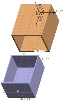
Click on the green plus “+” button to add a new planar constraint, and then pick the TOP datum planes on both models. The drawer should now fully line up with the opening in the drawer body, but it still sits out away from it. Click on OK to complete the placement, and the assembly will look like the following.

Now go to Mechanism mode using Applications, Mechanism and try dragging the drawer. You will notice that it will go in and out. The joint axis symbol for each planar connection is shown on the model.

Each individual joint axis symbol contains a rectangular block, two straight arrows, and one straight arrow with a rotational arrow around it. The two straight arrows are used to define the two open translational degrees of freedom. The straight arrow with the rotated arrow about it is used to define the rotation about the axis normal to the plane.
You can create motors that act on one or more of these individual degrees of freedom. We will not create one for this example, but you will for the exercise.
LESSON SUMMARY
A planar connection simulates an object that rests on a flat surface, but is able to translate in that planar surface and rotate about an axis normal to that surface.
Use other connection types (pin, slider, etc.) to control the other three open degrees of freedom, or connect up the component to others that have more fixed degrees of freedom (as we will see in the exercise).
EXERCISE
We are going to create a robot whose motion will be driven by one of its components that sits on a plane. Therefore, open up the Planar_Robot.asm assembly, which initially has only one component (a flat plate with a base for the rotating robot arm), as shown below.

The final assembly (prior to running the animation) is shown below.

The goal will be to have the blue wheel (PRobot_6) move in the plane in the following way.

Where the values in the parenthesis represent the following:
( dx, dy, dt)
Where:
dx = incremental change in the X direction from the last position.
dy = incremental change in the Y direction from the last position.
dt = incremental time change for the motion from the last position.
Therefore, (8,0,3) means that the wheel moves 8 inches in the X direction, and 0 inches in the Y direction for a span of 3 seconds. The X and Y directions are shown in the following figure.

HINT: You will only need to create servo motors for one component. PRobot_4’s position must be reset to be completely embedded into PRobot_3’s cylinder. All other components can remain at their default assembly location while bringing them in.
To view a movie of this animation as it should look from a TOP view, open the file Wheel_Travel1.mpg in your training directory.