|

Lesson Objective: In this lesson, we will go into more detail into the playback tool, looking at interferences, trace curves, etc. We will also learn about creating MPEG movies and considerations for this.

MPEG-1 FILES
When you are playing back an animation from an analysis, you have the ability to create a movie file. This movie file is created in the MPEG-1 format, a widely accepted format. Windows Media Player, Real Player, Quicktime, etc. will all play this type of file.
The only thing you have to consider is the default playback frames per second that these applications use. For this lesson, we will concentrate on Windows Media Player files, because that is the most commonly used player with computers today.
Windows Media Player plays MPEG-1 files back at a rate of 24 frames per second. This will have a significant impact on the time your movie takes to run. For example, suppose we create a movie that is supposed to realistically capture an exact motion of a robot loading and unloading an item from a shelf.
If you remember, the default settings for an analysis are:
· Start Time = 0
· End Time = 10
· Frames Per Second = 10
· Minimum Interval = .1
· Frame Count = 101
If we play this movie back in Windows Media Player, it won’t run for 10 whole seconds. In fact, it will only run for 4.2 seconds. How do I know this? The total number of frames in our movie is 101. The playback speed of Windows Media Player is 24 frames per second, therefore:
![]()
To get a true 10 second animation out of Windows Media Player, you need to have 240 frames in your animation, or in other words, you need to set your frame rate to 24 frames per second.
We will demonstrate this now.
EXAMPLE – FRAME RATE
Open the assembly entitled Frame_Rate, which will look like the following.
This assembly already has a snapshot created called Starting_Position, that marks the beginning of our animation. We will create a new servo motor, analysis and generate a movie from the playback results.
30 Second Animation
The goal for this first attempt is to create an MPEG movie that captures one complete rotation of the arrow in 30 seconds. Therefore, at 24 frames per second, we need to have 720 frames in our analysis.
The first thing we need to do is create the servo motor that
will generate 360 degrees in 30 seconds. Therefore, go to Applications,
Mechanism and click on the Create Servo Motor tool ( ![]() ). Create a new servo
motor called One_Rev, and select on the pin joint. For the Profile,
set the Ramp magnitude to A=0 and B=12, and then click on
the graph icon. We should see the following.
). Create a new servo
motor called One_Rev, and select on the pin joint. For the Profile,
set the Ramp magnitude to A=0 and B=12, and then click on
the graph icon. We should see the following.
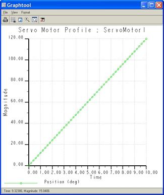
The default range for the “Time” scale is 10 seconds. At Time=10 seconds, we can see the magnitude is 120 degrees. Therefore, at 30 seconds, it should be 360 degrees. To know for sure, we can go to Format, Graph from the menus at the top of the graph window, which looks like the following.
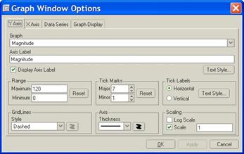
On the Y Axis tab (which is already selected), we will change the Maximum Range value from “120” to 360, as shown below.

On the X Axis tab, change the Maximum Range value to 30, as shown below.
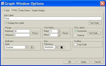
Then, click on OK to update the graph, which will now look like the following figure.
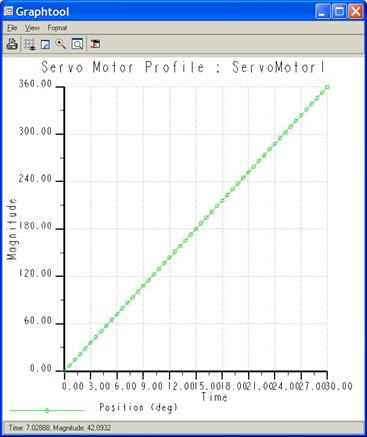
We can clean this up more if we want to using the graph settings, but we can see from this graph that at Time=30, we have a magnitude of 360 degrees. Close out of this graph window, and then click on OK in the servo motor definition window. Close out of the Servo Motors window.
Now, we need to create an analysis. Therefore, click on the
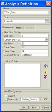
Analysis tool ( ![]() ). Rename the analysis to 30Sec_Spin,
and change the following settings:
). Rename the analysis to 30Sec_Spin,
and change the following settings:
· Start Time = 0
· End Time = 30
· Frame Rate = 24
This should automatically create the frame rate of 721 (note – it will actually turn out to be 720 when the animation is created).
Set the start condition to use the Starting_Position snapshot. The window should look like the following.
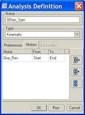
Go to the Motors tab, and make sure your servo motor is set to go from the start to the end, as shown below.
Then, click on Run. The animation should go through one complete turn. Once the animation is done, click on OK to close out of the Analysis Definition window, and then click on Close to close the Analyses window. Before we do our playback, we will re-orient the model. Go to a FRONT view, and zoom out so that if you were to drag the arrow around, you would see it all the way around. The reason we are doing this is because when we create an MPEG from Mechanism, it takes a snapshot of the working window at each frame. If your model goes off the screen, it will go off the screen in the MPEG movie that you create. Once your model is in the FRONT view and zoomed properly, we can go to the results window.
Go to the playback tool ( ![]() ) and press the play button in the
upper left corner. You will get the following window.
) and press the play button in the
upper left corner. You will get the following window.

At the top, you can see the total number of frames for this animation is 720. Down in the lower left corner, there is a button entitled Capture. Click on this button. It will bring up the following window.
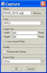
At the top of this window, you can enter a new name for the MPEG movie. It defaults to the name of the assembly. We will call our movie 30_second.mpg. The image size of the movie is automatically selected based off of the aspect ratio of your working window. I would leave this alone.
In the Quality section, you have the ability to render your movie. This will enable Pro/PHOTORENDER to render each frame individually. It creates a nicer movie, but it takes a long time (the amount of time it takes to render one frame times the total number of frames – 720 in this case). We will leave this unchecked for now.
Finally, you can specify a frame rate at the bottom. You have three choices: 25, 30 or 50. Honestly, you are better off for Windows Media Player leaving it at the default of 25. It will get you closest to the playback rate of 24 frames per second.
Once you are ready, click on the OK button.
IMPORTANT: It is a good idea to turn off any screen savers or power settings that may interrupt the recording of the MPEG movie. Since it does a series of “screen captures” (unless you use the Photorender option), any files you open, and windows that pop up in front of the screen, etc. will be incorporated into the movie.
Once the movie is done, click on Close from the player. Save your results file, followed by Close from the results playback window. Go to your working directory and play the movie. It should open up in Windows Media Player, as shown below.

If you notice, the total time listed in Windows Media Player is 29 seconds instead of 30 seconds. This might have something to do with the fact that we record the 720 frames at 25 frames per second, and then play it back at 24 frames per second, but it is very close to what we need.
TRACE CURVES
One of the helpful tools in Mechanism is the ability to create a trace curve to capture a particular point’s path on the model as it goes through the motion. We will use this same assembly to demonstrate this.
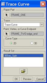
To get to the trace curve functionality, we will go to Mechanism, Trace Curve from the menu bar. It will bring up the following window.
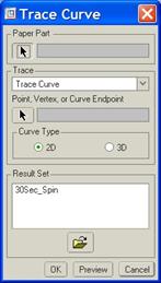
The way a trace curve works, is you first specify a “Paper Part”. This is one of the parts in the assembly that the datum curve will be created in. It can not be the same part that contains the point or vertex that is creating the curve.
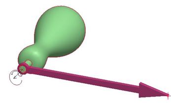
It is a good idea to use a non-moving part, such as the ground for this. Therefore, we will select the Frame_One.prt part (the green handle). Then, we are asked to pick a datum point, vertex or curve endpoint on a different part that will create the curve. We are going to pick the front vertex at the end of the arrow, as shown below.
Considering that our arrow stays in a two-dimensional plane, we can leave the default of 2D curve. Otherwise, we would need to pick 3D curve if this vertex were traveling in more than two directions.
The last thing we need to do is specify the results set that contains the animation information. We already saved our set for the 30Sec_Spin animation, so we can select that one, as shown in the next figure.
If you were just opening up the assembly, you could retrieve in an existing set. If you did not have a results set, you would first need to run an animation, and then generate a results set to pick.
Once we have the result set picked, click on OK. It will (transparently) go through the motion and generate the curve, which looks like the following.

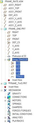
If we show features in our model tree, and expand the Frame_One.prt component, we can see the feature that it now contains for this trace curve.
Go ahead and save this assembly.
So what does a trace curve do for us? It gives us a physical representation of the motion of a vertex or point on a component. That curve can be used to generate other parts, or help us define the shape of a cam, etc. It can even help us identify space necessary to work around our moving assembly.
Now, we will look at another tool that also helps us identify space claim information, called a Motion Envelope.
MOTION ENVELOPE
A Motion Envelope is a lightweight part that gets created in the context of a mechanism assembly. It can be assembled into other parts to help work around the necessary space required for that assembly as it is in motion without having to bring in the whole assembly itself.
The way it works is pretty simple. First, go back to the
playback tool for our assembly ( ![]() ). At the top of this window, there
is an icon at the right end of the toolbar that looks like a blue envelope.
The tool-tip that appears if you leave your mouse over it says Create a
motion envelope.
). At the top of this window, there
is an icon at the right end of the toolbar that looks like a blue envelope.
The tool-tip that appears if you leave your mouse over it says Create a
motion envelope.
Click on this and you will see the following.

By default, all the components in the assembly are selected. We will leave this alone. We can also see that it automatically ignores skeletons and quilts. This is good, because we might have large surface or datum features in our assembly that are only there to help us build geometry, but doesn’t actually appear in the real assembly that is manufactured. Therefore, we will leave these checked.
The default type of part created is Part, which is a basic Pro/ENGINEER part. We will leave this alone as well, but you can see that you can create a light-weight part (LW Part), an STL file or a VRML.
The file name given to the part is listed in the field at the bottom. We will leave this name alone. The last thing we will talk about is the Quality field at the top entitled Level. It is currently set to 1.
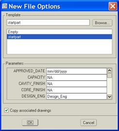
For now, let’s accept this and click on the Create button at the bottom. A new window will open indicating which part we are going to use as the basis to create this part, and we should see startpart (or our current start file – depending on division) selected by default, which is what we want.
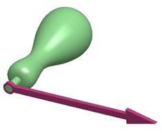
Click on OK to continue, and it will create the part in the background. Once it is finished, the message window will say “FRAME_RATE_ENV0001 has been saved.” Close this window, and then close the playback window. We will open up this part, which will look like the following figure. NOTE: You may get a message saying that you have not saved your results before exiting Mechanism. That is okay.
This is really a rough representation of the assembly as it goes through the motion. In some cases, this is adequate, in others – not so much. It really depends on the level of detail you need up close to the assembly.
Just for fun, go back to the assembly, re-enter mechanism mode, and then go back to the results window again. If you do not see the Create a motion envelope icon, you may need to re-read in your results file. If you do not have a results file, you will need to re-run the analysis.
In the motion envelope window, click on the up arrow next to the level 1 field. You will get the following message.
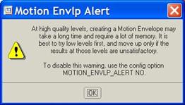
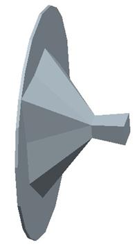
We will go ahead just to show you that it really does take a long time to generate a high-quality motion envelope. Once you click on OK, bump up the quality level to 10, and create the Frame_rate_env0002 part. After a good length of time (probably up to 10 minutes depending on the speed of your computer), the part is created, and when you open it, it looks like the following.
NOTE: I turned the display to no-hidden line to see it easier when zoomed out. If you zoom in while shaded, you can see the part that is created. It obviously had a harder time generating the triangular surfaces for the greater detail, but you can see that the overall shape of this part is a lot closer to the assembly than the first one.
Go back to the assembly and save it, and then close it.
INTERFERENCE DETECTION
Perhaps one of the most useful things about mechanism is the ability to identify interferences through a complex range of motion that might not be easily detected otherwise.
If you think back to how you traditionally do interferences without mechanism, you would have to modify an angle or dimension to update the location of components, run an interference detection, and then continue on with this process.
You hope that you manage to pick a dimensional increment that happens to put the assembly into a configuration where an interference occurs, but not always does this happen.
The mechanism animation tool has an interference check built into it that you can run to test the range of motion. Granted, it is still only calculating per frame, but your chance of finding the interference is greater than without it.
To demonstrate this, we will go back to the fan assembly.
Fan.asm
In the fan assembly, enter into Mechanism mode. Go to the analysis tool and delete the existing analysis. Then, go to the servo motor tool and we will edit it to contain the following values:

We are going to have this fan go through one complete rotation for the 10 second animation.
Next, go to the Analysis tool and create a new analysis called Interference, and set it up as follows.

Then, click on Run. Do not worry if the fan is moving counter-clockwise. That is okay for this demonstration. Once the analysis is complete, click on OK, followed by Close, and then go to the results window.
In the results window, we have some options at the bottom, as shown below.
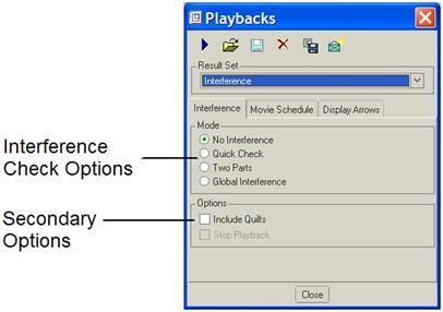
The Mode options are as follows:
· No Interference – Does not perform any interference check during playback.
· Quick Check - Performs a very low-level check for any interference (would work well in this case, because we have very obvious interference)
· Two Parts – Check interference between only two parts (we only have two parts in our current assembly, but this would be good if we know that out of a larger assembly, there is only potential to have interference between two parts)
· Global Interference – Check the entire assembly for interference – full check.
The Options selections are as follows:
· Include Quilts – Include any quilt surfaces into the interference check.
· Stop Playback – Automatically stops the animation in the playback at the first sign of interference. This is useful if the interference is so slight that you might not see it during the playback because the parts go fast enough to pass right through it in a short duration of time.
We are going to perform a Global Interference for this playback. We will leave the other options unchecked for this demonstration. When you click on the play arrow, it will calculate the interference for each frame, and then bring you the player controls.
As you play the animation, you will be able to see the areas of interference as they are encountered highlighted in red, as shown in the following figure.
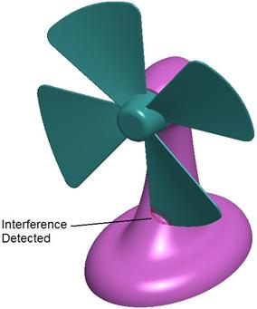
You can even use the Capture button to get an MPEG file that shows the interference. To see this, open up the FAN_Interference.mpg file in your training directory.
Go ahead and save the playback file for this analysis, and then save and close this assembly.
LESSON SUMMARY
You can create MPEG-1 movies of your animations that can be played with Windows Media Player or other popular media players. The key to getting your animation to run for the exact amount of time is to use a frame rate of 24 frames per second. If the total animation time is not important, you will not need to worry about this.
Some important tools that you can use in conjunction with playback are trace curves, motion envelopes and interference detection.
You can even create Photorealistic animations of your assembly.
EXERCISE
Go back to the Zero Refs assembly. Delete the existing analyses and servo motors. Create a new servo motor (called Open_up) and analysis (called 15Sec_Run) to open the lid 90 degrees over a span of 15 seconds.
Create an MPEG movie of this analysis. Next, generate a motion envelope at a quality level of 5 to see the entire space claim for this part during its animation.