Lesson 10

Lesson Objective: In this lesson, we will learn how to make multiple curve edits, copy curves, offset curves, and importing datum curves.

MULTIPLE CURVE EDITS
Suppose you have more than one curve endpoint that you wish to change the tangency condition to be the same type and same reference. For example, suppose you have two curves, and the four endpoints on those two curves need to be normal to the TOP datum plane.
Instead of picking each endpoint and changing the tangency condition, you could use the Ctrl key and select all of the endpoints so they highlight simultaneously. Then, when you set the condition for one of them, all of them set the same way.
To demonstrate this, open up the file entitled Multiple_Edit.prt. It will look like the following.

Edit the definition for the style feature. This style feature consists of four curves. Two of the curves are planar (on the TOP datum plane), and the other two are free (with soft points tied to the ends of the two planar curves).

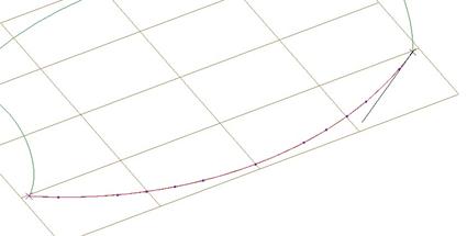
We will click on the curve edit tool, and then select one of the two planar curves. Then, hold down the Ctrl key and select the two endpoints on this curve. Next, (while keeping the Ctrl key held down), pick on the other planar curve and then its endpoints. You should now have four endpoints selected, and be able to see the four tangency lines, as shown below.

Hold the right mouse button down over one of the four tangency lines and select Normal, and then pick the RIGHT datum plane from the model tree. You will see the four lines adjust, as shown below.

Click on the middle mouse button to accept this change. Now, pick on one of the free curves. Hold down the Ctrl key and select the two endpoints for this curve. Next, pick on the second free curve, and then its endpoints. Once all of the endpoints are selected, we should see the four tangency lines, as shown below.

Hold down the right mouse button and select Normal and then pick the TOP datum plane from the model tree. The four tangency lines will adjust, as shown below.

You may notice that one of the tangency lines is going down while the other three are going up. If we were to drag that one line up, we will notice that all four move at the same time, as shown below.

To move just the one line by itself, first click with the middle mouse button to finish the curve edit, and then pick on just the one endpoint with the curve edit tool and adjust its tangency length.
Multiple Point Move
Suppose you want to move several points simultaneously. You start off the same way that we just described for the last example. Select the curves that contain the points you wish to move using the Ctrl key.
Next, (while still using the Ctrl key), select the points you wish to move. Once all of the points have been selected, drag the last selected point, or go to the Point slide-up panel and enter X, Y, and Z values.
The points move in the same vector and magnitude as the one you are dragging.
To see an example of this, open up the file Multiple_Move.prt, which should look like the following.

We will start by editing the definition for this style feature. Next, go to a no hidden view to see what we are doing easier.
Click on the curve edit tool, and select the following two curves using the Ctrl key.

Once both curves are selected, keep the Ctrl key held down and select the top point on the left curve, followed by the top point on the right curve. You should see the tangent lines for both of these.

Now, hold down the Alt key (let go of the Ctrl key), and drag the right point up, as shown below.

You can see that both points moved at the same time. If you remember, we used the Alt key to translate the points normal to the active plane. Click on the middle mouse button to finish this curve edit.
Restrictions on Point Moves:
You can edit parents and their children at the same time. The three curves that sit on the active plane have children – the four curves that stick up from those curves. Those four curves have children – the three curves at the top of the style feature.
The center curve at the top and bottom of the style feature are children to the curves on their sides, because they use a Curvature influence from those curves.
Convert Multiple Curves
Using the same model, we will demonstrate how to convert multiple curves of the same type to a different type. In our current example, we have three curves that appear to be on the active plane. These curves, however, are all Free curves, not Planar.
We want to convert all of these at the same time to Planar curves. Therefore, go to the curve edit tool, and then select the three curves that lie on the active plane using the Ctrl key, as shown below.

In the dashboard, select on the option for Planar. The message window will prompt you to select a plane to use for these curves. Click on the TOP datum plane from the model tree. The curves will be converted so they are planar curves on the active plane. Now, click on the middle mouse button to finish this curve edit.
Offset Multiple Planar Curves
Now that the three curves at the bottom of this model are planar, we are going to shift them upwards by an amount of 50.
To do this, we will first click on the curve edit tool, and re-select the three curves again, as shown above.
Next, we will click on the Refs slide-up panel, which looks like the following.

Click on the check box for Offset, and type in 50.0 in the field provided. Click on the Enter key, and you will see the three curves shift up by 50, as shown at the top of the next page.

Click on the middle mouse button to complete this curve edit. Save and close this part.
Other Multiple Curve Edit Options
In addition to the ones demonstrated in this topic, there are other functions that can be carried out on multiple curves at the same time. These are:
· Change references for planar curves from one active plane to another. This is done by going to the Refs slide-up panel after all of the planar curves have been selected, and then select a new active plane. Be careful, because the curves are not merely projected onto the new active plane from the current one. It bases its orientation on the Horizontal and Vertical directions of the active plane, so it may rotate the curves.
· Perform combine or split operations on multiple curves.
· Change the soft point location (such as length ratio and value, offset from plane, link, unlink, etc.)
· Make selected parameters for the curves visible.
· Add or delete points for the curves, such as midpoint.
IMPORT CURVES
Many times, you will want to create curves using regular datum curve features. These curves can be used in Style, but you have no control over tangency or curvature for these, only style curves that connect to them.
In cases where you want the flexibility to manipulate datum curves in style, you will import them into style and they will get converted into actual style curves. Importing curves is also a great way to manipulate imported wireframe objects that otherwise you would not be able to modify.
NOTE: It is important to note that the shape of a curve may change once imported into Style as it is combined with other curves, split into multiple curves, or having its tangency line adjusted.
To demonstrate this functionality, open up the Import_Curves.prt part file. It will initially look like the figure below.

In the model tree, we can see that we only have one feature (other than our default datum geometry), which is an imported iges file that contains wireframe edges only.

To start with, we might want to change the color for this geometry so we can tell it apart from the style curves that we are going to create. Therefore, start by selecting all of the curves using the Geometry filter, and the Ctrl key to pick multiple objects.

Next, right mouse click over one of these selected curves, and select Properties. It will bring up the following window.

Click on the blue color square to bring up a window showing available colors.

We can create a new color, or select an existing one. We know that we don’t deal with the sheet metal green color very often, so we will go ahead and pick that color, and then select OK, followed by Apply, then Close.
The model will now look like the following.

Suppose this is imported geometry from Alias or SolidWorks, or some other non-Pro/E software. Also suppose that we need to change the shape of the large arc on the side to include a dimple.
Therefore, we will not be able to use the side curve “as is”, and it should be imported into the style feature to use it there.
If we are not changing the two end curves, then we can leave those alone. For the style feature, we are also going to add some internal curves that define the profile across the middle of this part.
Create a new style feature. When it opens, we will start by importing one of the two large arcs. We will only need to do one, because we are going to take advantage of symmetry in the model and only make half of it.
To import the curve, go to Styling, Curve from Datum. Select the front curve, as shown below.

Then, click on the middle mouse button to complete the import. You should now be able to see the curve sitting on top of the green curve that we started with, as shown below.

To start using this imported style curve, we will click on the curve edit tool and then select the curve. You will see that it has a bunch of points defined along the length of the curve.

The first thing we are going to do is convert this curve from a Free curve to a Planar curve in the dashboard. By default, imported curves come in as Free.
Once converted, zoom in on one of the endpoints, and try dragging it with the left mouse button. You will notice that it is not automatically linked to the arc at the end, as we can see in the following figure.

Therefore, we are going to hold down the Shift key, and then drag the point over until your mouse is sitting on the arc at the end. Because we are using a planar curve, this should create a fixed point at the intersection of the arc and the active plane. Do this for both sides, as shown below.
Remember what we said about curvature and the total number
of points? Go ahead and go to a TOP view, and click on the show curvature icon
(![]() ). Open up
the styling preferences, and change the size to 8.0 and set the display
quality to 10.0. You will see the following.
). Open up
the styling preferences, and change the size to 8.0 and set the display
quality to 10.0. You will see the following.

You can clearly see the dips and bumps in this curvature plot. Therefore, we are going to right mouse click over each of the points and select Delete. Once all of the points are deleted, right mouse click over the curve again and select Add Midpoint. Once the midpoint point appears, use the Shift key and drag it over to the green curve to snap it to the curve. This will create a soft point, and if you check to make sure your length ratio is set to 0.5, you will see that we have reproduced the original curve and have a smooth curvature plot at the same time.

Turn off the curvature plot. Now, if you recall, the reason we imported this curve instead of simply using the existing green curve is because we need to add a dimple in the middle. Therefore, we will start by right mouse clicking on the curve halfway between the left endpoint and the midpoint and select Add. Hold the shift key down and drag it until it snaps to the green curve with a soft point. Next, adjust the length ratio for this point to be 0.25.
Repeat this process to create another point between the midpoint and the right endpoint with a length ratio of 0.75. The result is shown below.

To create the dimple, hold the shift key down again, and drag the midpoint off of the green curve so it becomes a free point again. Go to the Point slide-up panel and adjust the X, Y, and Z coordinates to 0.0, 0.0 and 2.5 respectively.
The curve should now look like the figure at the top of the next page.

We can see that, to remain smooth, it caused the curve to bow out away from the green curves past the intermediate points. We can adjust this with the endpoint tangency lines.
Select the right endpoint to see the tangency line, and then right mouse click on that line and select the Align condition. When prompted to pick an entity to align to, click on the original green curve on the right half of the screen. Then, go to the Tangent slide-up panel, and adjust the tangency length to 0.25.
Repeat this for the left endpoint. The result is shown below.

This is a very good approximation of the original curve past the intermediate points. It will never be identical and still maintain the smoothness into the dimpled area.
Now that this curve is done, we are ready to sketch the two remaining curves. Click on the middle mouse button to finish the curve we were working on, and then click on the select active plane icon and pick the FRONT datum plane to make it the new active plane.
Click on the create curve icon and make sure it is set to Planar in the dashboard. Then, hold down the Shift key and select the left and right arcs. It should automatically place a fixed point on these arcs at the intersection of the active plane.
Then, go to a FRONT view, and adjust the tangency lines. For the right side, change the tangency line condition to Normal and select the RIGHT datum plane. Adjust its length to 2.0.
For the left side, change the tangency line to Free, and then open up the Point slide-up panel. For the Length, enter 0.75, and for the Angle enter 60.0. The result is shown in the following figure.

Click on the middle mouse button to finish this curve. Now, change the active plane over to the RIGHT datum plane and create a new planar curve. Pick on the last curve that we created and the imported curve with the SHIFT key to get fixed points on both of these.
Go to a LEFT view, and adjust the tangency line at the top to Normal and select the FRONT datum plane. Set its length to 1.0. Next, adjust the tangency line at the bottom to Normal and pick the TOP datum plane. Set its length to 1.0 as well.
The result is shown below.

Click on the middle mouse button to complete this curve. Now we can create our surface using the imported curve, two arcs at the ends and the middle curve as boundary curves, and the last curve that we made as an internal curve. The result for the surface is shown in the following figure.

Click on the blue check mark to complete the style feature, and then mirror the style feature about the FRONT datum plane to get the final model.

COPY AND MOVE
You can copy and/or move curves in Style. This functionality only works for curves of type Free or Planar. COS curves can not be moved or copied.
Move
This functionality allows you to reposition style curves based on global X, Y, or Z values, or relative to its current position. To demonstrate this, we will open up the Copy_Move.prt part file, which initially looks like the figure below.

We can see a large arc shaped curve about ¾ of the way along the two planar curves. We are going to move this curve. Edit the definition of the style feature.
Next, go to Edit, Move from the menu bar. When prompted, select the large arc curve, and then click on the middle mouse button. We will see the arc highlighted, and one of the endpoints will have an “X” on it, as shown below.

Down in the dashboard, we can see three fields for X, Y, and Z values. These are showing the location of the endpoint with the “X”.
![]()
We can enter exact locations in the fields based on the default coordinate system, or we can click on the Relative check box and enter incremental values based off of its current position. For example, if we wanted the point to move 1 inch from its current position in the X direction, we would click on Relative and then type in 1.0 in the X field.
You can also dynamically drag the curve just by using the left mouse button. Go ahead and drag this curve over towards the right, and you can watch the position update in the three fields. Stop it about 9 inches in the X direction, as shown below.

Now, go ahead and drag it all the way to the end so the X value is 10.0, the Y value is still zero, and the Z value is -5.0, as shown in the following figure.

Click on the middle mouse button to accept this move. You still have the option to move the endpoints of the curve the way we have been using soft point location values, etc.
Copy
Now, we want to have another curve at the center of our style feature. We already have two arcs at either end, therefore, we will copy one of these and move that copy to the center.
To do this, go to Edit, Copy from the menu bar. When prompted, select the arc at the left end (not the one that we just moved), and then click the middle mouse button.
We should see what looks like the arc that we picked highlight and one of the endpoints has an “x” on it just like we saw with the move operation.

If you drag this curve using the left mouse button, you will see that it is a copy of the curve sitting right on top of the one it was copied from. Move it out towards the middle, as shown at the top of the next page.

In the dashboard, type in a value of 5.0 for the X field. The Y field should still be at zero, and the Z field should be -6.5. The result in an isometric view is shown below.

We might think that this curve is perfectly centered, but if we go to a TOP view, we see otherwise.

We can also go to a RIGHT view and notice that we are no longer seeing a 180-degree arc, like the one at the end was, as shown at the top of the next page.

There is no need to worry. We can click on the middle mouse button to finish the copy operation, and then click on the curve edit tool and make sure that each endpoint (soft point) is at a length ratio of 0.5, which will center our curve, as shown below.

Next, adjust the tangent length for each endpoint to 3.25, which will give us our 180-degree arc, as shown in the following figure.

The benefit for using the copy command is that the endpoints are automatically tied to the two planar curves just as the original one was, and the tangency line condition for both endpoints is normal to the TOP datum plane, just as they were in the original. Minor adjustments had to be made, but it did save some time.
The final curve looks like the following.

Copy Unlink
There is another copy command in the Edit menu. This one creates a copy of the curve selected, but unlinks it from the same references. Therefore, it would create what we had before, but the endpoints would no longer be tied to the two planar curves.
To try this, go to Edit, Copy Unlink from the menu bar. When prompted, select the left curve that we copied before and then click on the middle mouse button. So far it looks the same as a copy command.

Now, try dragging this curve. Immediately you will notice that it maintains its shape and size, but it is not following the two planar curves at the bottom. Rotate your part and try dragging up, you can see that it is free to move in all directions, as shown at the top of the next page.

Finish this copy command by clicking on the middle mouse button, and then use a curve edit tool to look at the tangency line condition for each endpoint. You will notice that it is set to Free instead of Normal.
Click on the middle mouse button to complete this curve edit, and then delete this curve that we just created.
Proportional Update
Proportional update allows a curve’s free points to move in proportion to the soft points, thus retaining its shape proportionally while being edited.
To demonstrate this, we will first use the edit curve tool to the middle arc curve that we created earlier. Add a mid point and two additional points and locate them as shown from a RIGHT view.

Once you have the points created, go ahead and go back to a default view. Pick on the soft point that is on the wavy curve at the top of the style feature, and change its location using a length ratio of 0.8. This causes the soft point (and only the soft point) to move, as we can see below.

Click on the Undo button to return it back to the middle. Now, look at the dashboard, and you will see an option called Proportional Update, as shown below.
![]()
Place a check in this box, and then change the soft point location to 0.8 again. Notice the difference?

This time, when the soft point moved, the whole curve rotated to maintain the correct shape, and it scaled accordingly to account for the distance increase between soft points.
Go ahead and finish out of this curve edit, and then delete the center curve, so we are back to the figure shown at the top of the next page.

Copy and Move Shortcuts
Use the following shortcuts in conjunction with the select
tool (![]() ) to
move and copy curves.
) to
move and copy curves.
· Hold down the SHIFT and CTRL key and drag on the selected curves to move them.
· Hold down the CTRL key only and drag on the selected curves to copy and move them in the same operation.
To try this, go to the select tool and pick on the arc at the left of the model (in default view), and then try using the combinations above to create a new curve at the middle of the part.
LESSON SUMMARY
When working with curves in Style, you can manipulate multiple curves at the same time. This will save you time if you need to adjust the tangency direction and magnitude equal for multiple endpoints.
You can also copy, move or offset curves from existing ones or current locations. Use Proportional Update if you have any free points on the curve that you want to maintain their shape while moving around soft points.
Importing curves into Style will let you manipulate what might otherwise be static curve features, such as IGES data.
EXERCISE
Open up the model entitled Bowl. It will initially look like the following.

This part consists of an imported IGES file from Alias|Wavefront. Often times, IGES files created from Alias have problems with the surface and curve connections, and therefore, Pro/ENGINEER has a hard time dealing with them. Occasionally, you can use a heal geometry tool to try to fix the gaps. Many times, however, you may need to start a new part from scratch and not use the imported geometry.
In the Bowl model, we have already done some initial organization. Two layers have been created, one called Inner_Surfaces, and the other called Outer_Surfaces, as shown below.

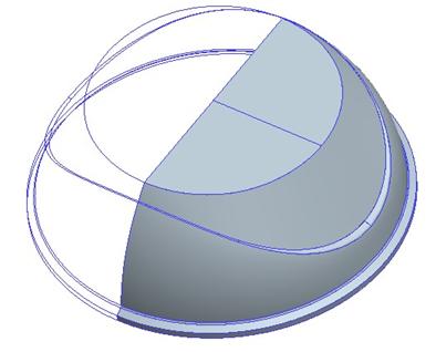
We can use these layers to turn off the curves that are either on the inside or outside of this bowl, to make it easier to work with the model. In this exercise, we are going to create a half-model of the outside surfaces using a single style feature, to end up with the following model.
ON YOUR OWN
If you finish this exercise and wish to try completing the entire bowl model, then create another style feature for the inside surfaces. Merge these two style surface models together, and then close it off. HINT: Because Alias|Wavefront curves are not perfectly planar, you may have to manipulate the midplane curves to get them to lie on the same plane before closing off the model or mirroring it.