Lesson 2

Lesson Objective: In this lesson, we will go through an example that demonstrates the basic steps to creating a surface from four boundary curves using the style feature.

EXAMPLE INTRODUCTION
For this example, we will create a single style feature that contains four style curves and a style surface. We will not worry about all of the details for each step, because we will get to the details in the upcoming lessons. For now, this shows the typical steps to using the style feature.
Launch Pro/ENGINEER Wildfire, and set your working directory to c:\people\ISDXTrain. Start by creating a new part called Style_Example. Keep the default datum planes turned on, but turn off any other datum features.
We will start by going into the style feature by clicking on the following icon in the feature toolbar.
![]()
This will bring up the toolbars and Styling menu that we saw in the first lesson. We are now ready to create our style curves.
NEW STYLE CURVES
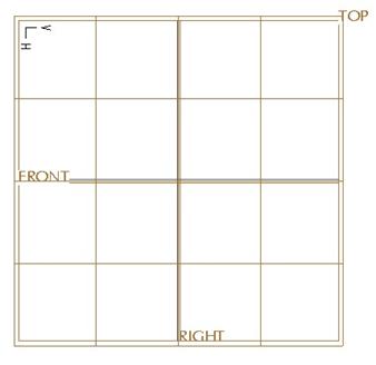
We will begin by going to a TOP view. We should already see a grid laid out on the TOP plane, as shown below. This grid is referred to as the Active Plane.
We will turn off the view of datum planes now to make it easier to see what we are doing. We will then click on the new style curve icon, which looks like the following.
![]()
The dashboard for the New Curve will appear, as shown below.
![]()
For this example, we will create our four curves on the existing Active Plane. Therefore, we will select the Planar option in the dashboard.
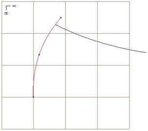
We will then use the left mouse button to pick three points, as shown in the figure below. As we click on point two, a straight segment appears between points one and two. When we pick on point three, the curve updates to remain tangent to all three points. This is just like a Spline in sketcher mode.
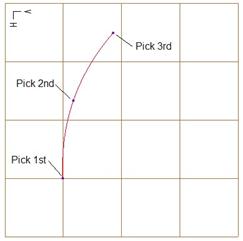
We can see a purple filled dot at each point we pick. Once we have picked the third point, use the middle mouse button to complete this first style curve. Do NOT click on the middle mouse button again, or it will finish the entire style feature. We want to remain active in this style feature.
Now, we will create a second curve. Click on the New Curve icon again, and this time, we are going to hold down the SHIFT key on the keyboard and move our mouse over the first curve as shown below.
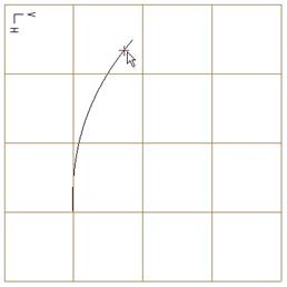
The SHIFT key enables us to dynamically snap to another object on our model. In this case, it will allow us to snap to the first style curve. We know when we are able to snap, because a little “+” symbol appears at the end of our mouse pointer (as we saw in the previous figure).
Once we click with the left mouse button, we will get an open purple circle that appears on the first curve in the location we specify. Continue to select the second and third point without holding down the SHIFT key. Once you select the third point, use the middle mouse button to finish this second style curve. Our resulting curve will look like the following.
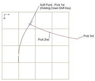
The first point of this second style curve is known as a soft point. A soft point can either be internal (does not lie on an endpoint of a curve), or an end point (lies at the endpoint of a curve). A soft point can be dragged along the curve on which it lies. To demonstrate this, we will use the Edit Curve tool.
EDIT STYLE CURVES
We will edit both of these curves so you can see how easy it is to change a style curve. Therefore, we will start by clicking on the Edit Curve icon, as shown below.
![]()
The dashboard for the Edit Curve tool looks like the following.
![]()
We will see all of the different aspects of this dashboard in a later lesson. For now, we will concentrate completely in the working window. We will start by picking on the first of the two style curves that we created. When we do, it highlights in red, and the three purple curve points appear, as shown in the figure at the top of the next page.
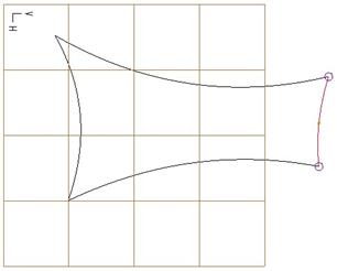
We will click on the third point (top endpoint) and drag it out towards the left to the approximate location shown in the following figure.
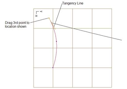
We will notice two things when we do this. The first is that the second style curve (since it was tied with a soft point to the first) also moved. The second is that a small yellow line appears at the endpoint of the first curve that we moved.
This line is called a Tangent Line. It is used to determine the tangency for the endpoints of a style curve. Any internal points on a style curve derive their tangency automatically, and can not be changed. Only the end points for a style curve can have tangency conditions set. We will see this a little later in this lesson.
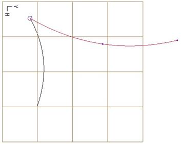
Now, with the edit curve tool still active, click on the second style curve so it becomes active, as shown in the figure at the top of the next page.

Drag the first point (the one with the soft point) until it stops at the end of the first style curve, and then drag up the third point (the opposite end point) to the approximate location shown in the following figure.
STYLE CURVE 3 & 4
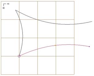
We will go back to the New Curve tool and create a third style curve. For the first point, use the SHIFT key to snap to the first style curve, and then sketch the other two points. Use the Edit Curve tool once you are done sketching the three curve points to make sure the first point is at the end point of the first style curve.
Style curve 3 should look like the figure at the top of the next page.
Style Curve 4 should have a soft point at the first point and third point. Place point 1 on style curve 3, and point 3 on style curve 2. Use the Edit Curve option to ensure that these are at the endpoints. This curve will look like the following.
Now that we have all four of our style curves, we will create a style surface.
STYLE SURFACE
We will begin by selecting on the Surface tool, which looks like the following icon. We should still be in the same style feature. We have not finished it yet.
![]()
The dashboard for the style surface tool initially looks like the following.
![]()
All the options are currently grayed out until we pick the style curves that represent the boundary of our surface. Therefore, we will start by selecting the first style curve that we made, then hold down the Ctrl key on the keyboard and select the other three in a clockwise direction.
NOTE: You can pick the boundary curves in any order. For consistency, we will pick them in a clockwise direction, as shown below.
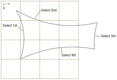
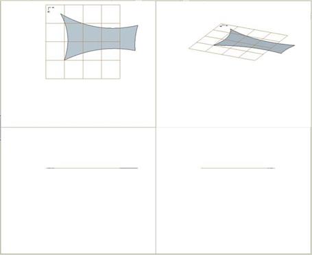
Once we are done selecting all four curves, we will see a surface appear through these four style curves, as shown in the following figure.
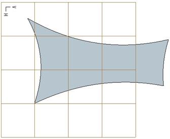
If you recall, we made all four curves lie on the Active Plane using the Planar option. If this is all we really wanted, we could have used a Fill surface instead. We are going to change this, but first, rotate the model a little bit to see that it truly is a planar surface at this time (see the figure at the top of the next page).
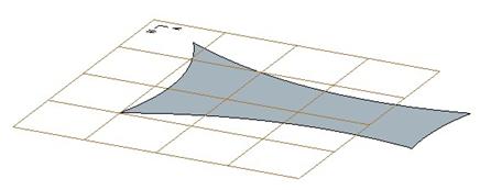
We will edit the first and fourth style curves to add some depth to this surface.
EDIT CURVES W/SURFACE
One of the tools that makes working in ISDX easier is to show viewpoints. Currently, we have been working in only one viewpoint. We can rotate the model if we need to, but it is often easier if we need to make changes in multiple orientations, to see a four-viewpoint view.
To do this, click on the following icon in the system toolbar.
![]()
This will change the working window into four quadrants, as shown below.
The upper left quadrant is a TOP view, the lower left quadrant is a FRONT view, the lower right quadrant is a RIGHT view, and the upper right quadrant is an isometric view.
We will go back to the Edit Curve tool, and select on the first style curve that we created. It will highlight in all four quadrants. In the dashboard, we need to convert this curve type from Planar to Free. By doing this, we will be able to move the points away from the Active Plane.
In the message window, we will be prompted to confirm this conversion, as shown below.
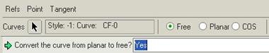
We will click on Yes to proceed. In the RIGHT view quadrant (lower right), drag the middle point of this curve up to form an arc, as shown in the following figure.
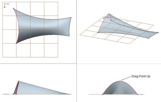
You will be able to dynamically watch all four quadrants update as you do this. Now, we are going to select on the fourth style curve, convert it to Free, then drag its center point up about halfway between the active plane and the curve that we moved before. Do this in the RIGHT view since it is easier to see the point and the direction we are dragging in this quadrant.
The result is shown at the top of the next page.
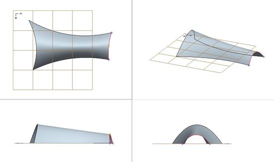
Now that we have moved the first and fourth style curves to form arcs, we will adjust the boundary conditions of these curves to ensure a normal condition with the Active Plane.
TANGENCY LINE
First, click on the viewpoint icon again to return to a single viewpoint, turn on the display of datum planes, and rotate your model (if necessary) to see the following view.
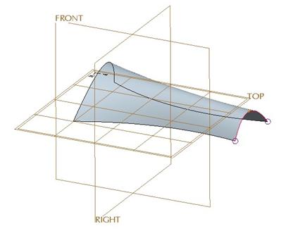
With the Edit Curve option still active, and the fourth curve still selected, pick on the first end point with the soft point (touching style curve 3). We should see the tangency line appear, as shown in the figure at the top of the next page.

We will place our mouse over this line, and then hold down the right mouse button to see a list of options to define tangency. We will select the option Normal, as shown in the following figure.
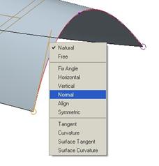
Once we select Normal pick on the TOP datum plane. The tangency line should automatically snap to a vertical line (or perpendicular to the TOP plane), as shown below.
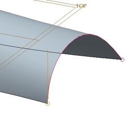
Repeat this for the other endpoint on this same curve, and for the two endpoints on the first style curve. When we are done, our surface should look like the figure at the top of the next page.
Now, we are going to copy the fourth style curve to create an internal curve to this surface.
COPY STYLE CURVE
Go to the Edit Curve tool, and then select the fourth style curve (the smaller arced curve). Once it is highlighted, go to Edit, Copy from the menu bar. The newly copied style curve will sit right on top of the curve from which it was copied, and a purple “X” appears on one of the endpoints, as shown below.
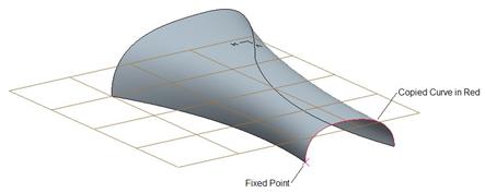
The “X” represents a fixed point. Usually, Fixed points are the internal points to a style curve (such as the second point in each of the curves). As we move this new style curve to its new location, we will see the fixed point turn into a soft point (with the open circle).
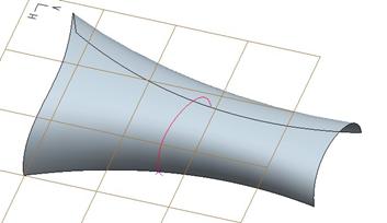
Using the left mouse button, drag this new style curve along the length of the surface, you should see the two endpoints riding along the second and third style curves. Drag it approximately half way along the surface, as shown below.
Once you have the curve there, go to the Edit Curve tool again, and switch over to a four-viewpoint view. Move the three points on this new style curve (without holding down the SHIFT key) until you get the following.
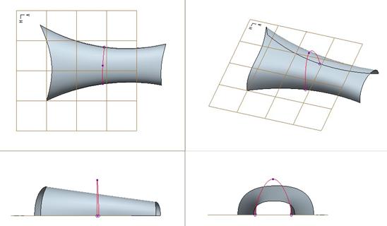
Once you have the new style curve looking like the one above, click on the middle mouse button to finish editing it. Now we will make it an internal curve to the style surface.
INTERNAL SURFACE CURVE
Start by going back to a single viewpoint view. Click on the surface to highlight it in red, as shown below.
Hold down the right mouse button, and select Edit Definition. This brings back up the surface dashboard, as shown below.

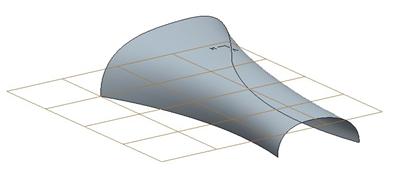
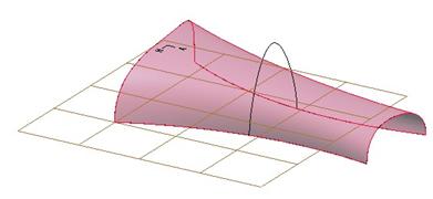
Just to the right of the word Internal, select on the black arrow, and then select the new style curve that we just copied. Once you select the curve, click on the middle mouse button. The curve will be added as an internal curve, and the surface will update automatically, as we can see in the following figure.
We will click with the middle mouse button to finish out of this surface edit. The last thing we need to do is to regenerate our entire style feature.
REGENERATE STYLE FEATURE
Before you finish out of the entire surface feature, you should regenerate it. In the system toolbar, you will see the regenerate icon, which has a red, yellow and green circle. One of these circles is larger than the others. If the green icon is larger, that means that the style feature is fully regenerated. If it is yellow, as shown below, we will need to click on this icon to regenerate the feature.
![]()
As we can see in our toolbar, the icon is yellow, so we need to click on it to regenerate it. When we do this, it will look like the following.
![]()
Once it is fully regenerated, we can click on the finish icon (shown below) to complete the style feature.
![]()
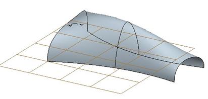
The completed style feature looks like the following.

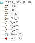
The model tree shows a single style feature, as we can see in the following figure.
Save and close this part.
LESSON SUMMARY
This lesson demonstrated some of the key elements to working with style curves and surfaces. In the remainder of the lessons, we will see these different elements in their entirety.